
I wanted a work space that includes:
- Power (5, 9, 12, 24 vdc)
- Integrated oscilloscope and logic analyzer
- Control panel switches pre-wired as input and at lease one LED as output
- A main power switch
- Space for an Arduino
Finally, this weekend I set aside time to build my dream breadboard workstation
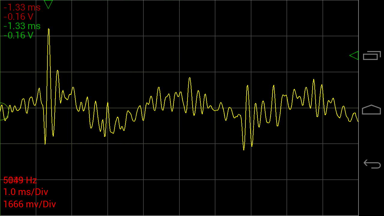
Oscilloscope
Although I have a nice oscilloscope I found this really impressive miniature oscilloscope that also has a 8 channel logic analyzer function.http://www.gabotronics.com/oscilloscopes/xprotolab-plain.htm

I imagined that I could integrate this scope with a bread boarding station. I got one at:
http://www.amazon.com/Xprotolab-breadboard-Oscilloscope-Waveform-generator/dp/B00HWZSAPI?ie=UTF8&psc=1&redirect=true&ref_=oh_aui_detailpage_o00_s00
The oscilloscope is mounted to a right angle acrylic bracket with a set of probes. Well not probes rather these test clips:
http://www.amazon.com/Anycubic-Quality-Analyzer-Folder-Saleae/dp/B014PEB4ZG?ie=UTF8&psc=1&redirect=true&ref_=oh_aui_detailpage_o07_s01

The the Oscilloscope is mounted on a acrylic angle bracket that is screwed to the underside of the base. The clip wiring it restrained to that bracket. Slots were milled in the acrylic to accommodate connecting the clip wiring. The entire bracketed scope can be removed if I want to use it in another location.
This wiring schema keeps the scopes probes short and above the breadboard and out of the way.


Tablet Application
The scope connects to my tablet using this software and an OTG cable:https://play.google.com/store/apps/details?id=com.nfx.noscpro&hl=en
You can find a variety of OTG cables on amazon.
The tablet is held with a 2 x 4 that has a 10 degree slot cut in it to the size of the tablets thickness.
Note: I also like to use other tablet based test equipment so this setup affords me access to spectrum analysis, function generator etc.
Mechanical packaging:
I don't have drawings for the mechanical parts because I designed them on the fly as the build evolved.The based frame is made from some solid surface (SS) left over from the new kitchen. SS is easy to cut and it can be conveniently tapped eliminating lots of fasteners.
The control panel is fabricated from acrylic sheet (Home Depot) and bent using a shop-made hot wire acrylic bender. "Google" "Bending Acrylic" if you want to build one.
Electrical parts:
The base bread boards is made from 4 of these:http://www.amazon.com/BB830-Solderless-Plug-BreadBoard-tie-points/dp/B0040Z4QN8?ie=UTF8&psc=1&redirect=true&ref_=oh_aui_detailpage_o00_s00
Four is probably more than I need but I like to prototype stuff and leave it set up until I have converted it to whatever the operation format is going to be, usually a one-of-a-kind soldered breadboard.
Power:
The best power setup i found is to use mini/micro USB for 5vdc and 2.1mm jacks for all other DC. All my power supplied have been fitted with these male and female jacks using these adapters:http://www.amazon.com/JACKY-5-5mm-Female-Connector-Camera/dp/B00JMVLTA8?ie=UTF8&psc=1&redirect=true&ref_=oh_aui_detailpage_o01_s00

The 3 rear power jacks are for other voltages than 5vdc such as 9vdc, 12vdc and 24 vdc. They are wired though the main power switch and color coded wires are brought to the upper left of the breadboard for distribution.
 These jacks are: 5.5mm x 2.1mm Power Jack Socket Female Panel Mount Connectors from here:
http://www.amazon.com/5-5mmx2-1mm-Power-Socket-Female-Connector/dp/B00N41C47E?ie=UTF8&psc=1&redirect=true&ref_=oh_aui_search_detailpage
The 5vdc is supplied by a micro USB connector breakout board. I like to use 5vdc bricks for my logic power. I think the breakout board came from Sparkfun.
All the power is routed through the main power switch ( a 4 pole double throw I found in my stash) for those moments when you smell smoke and want to cut all the power.
 Control Panel:
I have struggled for some time with making it easy to add switches into a prototype and then I landed on simply jerking a panel from a old DVD player. This was mounted on the base, it includes 3 buttons and one LED that are wired down to the breadboard on a .1 inch connector strip.
Can't live without an Arduino:
A "biggie" Arduino is mounted on the lower left for those times when I need more compatibility or shield capability, "Arduino" style.Final configuration

No comments:
Post a Comment