Laser Response Characteristics
I moved the research that I have been doing into "laser response" to this post to capture it in a more focused way.
Understanding the lasers response is an important part of getting to the best engraving control possible. The engraving control basics are described in Engraving-and-pwm-control.html.
Understanding the relationship between the HV power (voltage and current), the tubes gas discharge characteristics and the lasing process of the C02 is integral to an understanding of how to optimize digital control of its power.
Donate:
Please consider donating (button to the right of this post).Your donations help fund additional research, tools and parts that I will return to the community as information. For other information on the K40-S build use the K40-S BUILD INDEX with schematics as a source of information
Links to Related Posts
- First attempts at measuring light output
- Engraving-and-pwm-control.html
- K40-laser-power-supply-control-take-2.html
Electrical Modulation of a CO2 Laser
"Low frequency modulation can be achieved by pulsing or chopping the electrical power to the discharge. As the frequency is increased, the effect of the varying input decreases and above a few kHz, disappears entirely. The output of a DC or RF excited CO2 laser are both CW beams.(From: David Toebaert (olx08152@online.be).)
This remark really holds for any kind of CO2 laser (the effect gets worse at higher pressure). It's just nature: it takes time for the molecules to 'meet' one another causing the delay. For a laser at 100 mbar (around 76 Torr) and a typical gas mix, the cut-off frequency is about 3 kHz. Above that the modulation of the input power is strongly damped and hardly visible anymore in the output power.
Simply think of the discharge as a *low pass filter for the input power, no matter how you excite the discharge. Of course, it's possible to modulate the input power at much higher frequencies (e.g. an RF supply can easily be modulated up to 100 kHz, that is, the Mhz signal is modulated at 100 kHz), but from the point of view of wanting to modulate output power, it makes no sense. Maybe it's beneficial for other reasons (e.g., discharge stability)."
*Whats a low pass filter?
The Effect of Modulation Cutoff Frequency
The article above says that the laser cannot transfer input power changes that occur at a rate > than 3kHz. That means that the max time between changes that will be useful is: 3kHz = 1/3000 = .00033 = 330 us.This means that in the model above the suggested pwm period (200us = 5kHz) is longer than the response time of the lasers gas ionization.
If that is true then:
- The PWM period needs to be much longer or the gantry slowed down considerably
- The much faster times I measured (2us) by monitoring current suggests that it is not a indication of the speed of light output. Is the current flow during ionization much faster than the light output?
Laser Gas Discharge Characteristics
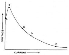 |
| Negative Resistance |
The hypothesis used in testing (above) and modelling; that the current flowing through the laser tube can be used as a faximile of the response of its light output does not track with the above modulation information :).
Laser Power Sources
Electric Discharge

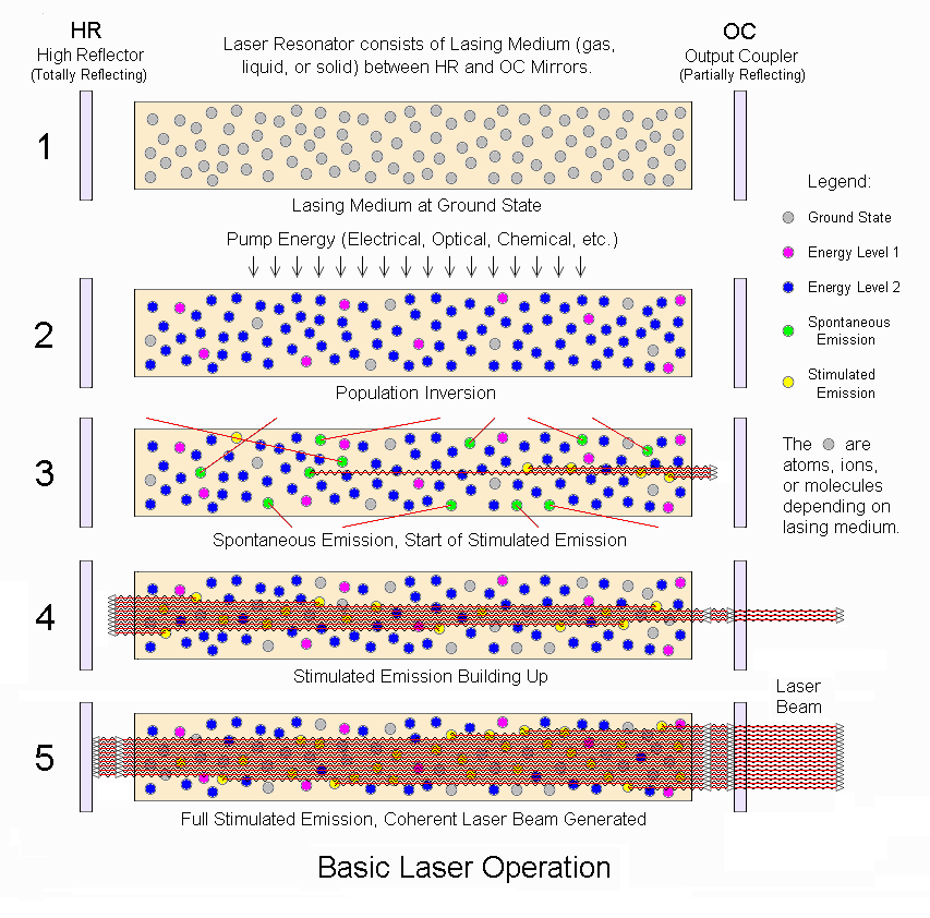
Pumping the Laser
This video shows measurements of response speeds in the 4ms region.
Laser Operation
Lots of info here:
CO2 Info Summarized From Links
Gas mixture & its function:
13.5% N2 : excited by gas discharge (pink glow) collides with and moves CO2 to level 3
9.5% CO2: molecule that lases at energy level 3-2.
77% He: collides with CO2 at level 2 and then collides with tube walls for cooling
2% H2: gas discharge disassociates CO2 into CO and 02. H2 mixes with CO & O2 to regenerate CO2
Ionization Voltage: 25 KV
Voltage at lasing: 13-15 KV
Negative resistance: 200-300K
Breakdown voltages
https://en.wikipedia.org/wiki/Dielectric_gashttps://en.wikipedia.org/wiki/Dielectric_strength
CO2: Air *.95
Air: 3,000,000 V meter
Laser Tubes
Synrad 40 W Lasers: Specifies a 100us rise time.
References To Aricles and Previous Work
https://en.wikipedia.org/wiki/GrayscaleUnderstanding CO2 lasers
Principles of plasma discharge
Dynamic PSpice Model of C02 Laser Tube
Gas Laser Electronics
Basic Laser Principles
-----------------
Enjoy and leave comments and discussion;
Maker Don


