The Laser Head
I have a habit of overcomplicating my first prototypes and the laser head in the MoBeam is no exception. This is all part of the learning process and the willingness to "iterate".
The original design included a plastic cage to allow the laser head to slide up and down fastened with thumbscrews. https://donsthings.blogspot.com/2021/09/l7x-vertical-adjustment-slide.html
As I climbed up the learning curve I found these things that helped me get to a simpler solution
- You can purchase a Laser Diode head mounting bracket
- A refrigeration capillary tube is a good choice for routing air assist
- The head and the air assist must be adjustable for both G8 and G2 Lenses
- The FL for the G8 is 30mm.
- The FL for the G2 lens is 10mm
A Simpler Head Mounting Design
This design replaces my original vertical adjustment approach
 |
| New |
 |
| Old |
Air Assist
An air assist nozzle was implemented using a piece of capillary tube that I salvaged from my HVAC replacement last summer. You can get tubing here: https://amzn.to/3q55qMa
The tubing is held to the laser module with two magnets that hold it to a piece of sheet metal when in operation. The sheet metal is screwed to the face of the laser module. This setup allows the nozzle to be adjusted up/down when moving the laser module for different lenses.
Existing mounting plates
These plates came with the unit. The black plate is used to cover the belt and carriage wheel access holes giving a flat surface for the new adapter plate to mount.
New Adapter Plate
The height adjustment plate is mounted to the face of this Lexan plate from the back. This plate is mounted to the carriage via 15 mm cap head screws & the supplied thumbscrews. These fastners sandwich the existing and new mounting plates together and to the carriage.
Height Adjustment Plate
This Laser Module Mount Holder Spring Clamp assembly was purchased from NEJE. This assembly holds the edges of the laser module with a spring-loaded clamp. The laser module can be adjusted vertically by loosening the cap screw sliding the module up/down and then re-tightening the screw.
My process to adjust for FL is to place a precision block under the lens, loosen the clamp, slide the head until it interposes the block, and then tighten the clamp. This approach is simple and accurate. I plan to use two lenses, a G8 and G2 dictating that the head be able to be adjusted a delta of 20mm.

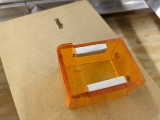
Optical Sheild
The optical shield design originally included a disk that also served as a means to rotate the lens for focus. https://donsthings.blogspot.com/2021/10/mobeam-focus-with-safety.html
Testing revealed that the lens can be adjusted one time for fine focus and then the entire head moved to achieve final focus. This is especially true of the 30mm (F8) lens.
After measuring and calculating the size of the shield I decided to attach it below the laser module with two magnets. This way the head can be adjusted down inside the shield for the short FL lense leaving the optical shield in one place.
It is important to note that MoBeam is designed so that the target material is always below the focal plane. Therefore the head only needs to be moved for lens changes.


Watch it in action!!!
Enjoy and please comment,
Don
Laser cleaners for sale is popular due to their prominent advantages.
ReplyDeleteAn HDPE Duct Spacer is a small yet crucial component used to separate and organize cables within duct systems. It ensures that cables are evenly spaced, preventing them from rubbing against each other and minimizing the risk of wear, tear, or overheating. Made from high-density polyethylene, these spacers offer excellent mechanical strength, resistance to corrosion, and a high degree of flexibility, making them suitable for use in a wide variety of environments.
ReplyDelete