INSTRUCTIONS:

Check out the new MoBeam posts! To find K40 conversion information use the "INDEX", "SEARCH" or "LABELS" sections in the sidebar.
Showing posts with label K40 Sensors. Show all posts

Monday, March 5, 2018

K40 Exhaust Air Sensor

How do you sense that your exhaust air is working?

My evacuation air system uses a pretty quiet blower and is controlled by a switch on my machine control panel. While working on the machine I noticed the blower was not working but had no way to tell for sure since other than the cabinet its a closed system. Opening the cabinet certainly worked but I wondered how hard it would be to build in a sensor. 
I have to admit this got out of control and one could easily argue that this problem did not need to be solved. But I cannot pass up a challenge to solve a problem that I have not yet solved.


Donate:

Please consider donating (button to the right of this post).
Your donations help fund additional research, tools and parts that I will return to the community as information.
For other information on the K40-S build use the  K40-S BUILD INDEX with schematics

The design

I started the design with the expectation that I could use a micro-switch with a flag on it like is used in furnaces. Turns out that it took much air to activate the switch and also blocked the airway. I also considered using a furnace air pressure switch but was not sure if had enough flow to activate this type switch. I will probably try one of these later although they are expensive.

After tinkering at the bench I decided to use an air vane, magnet and hall effect switch assy. to sense the air. The vane would sit in the air stream and an arm with a magnet activated a hall effect and amplifier that would in turn turn on an led. I powered the hall effect from a 120V to 5V switcher module I found on Amazon. 

Perhaps overkill but now I can tell if my exhaust air is on and it was a fun project. All other approaches were in excess of $100, this one cost me about $10 out of pocket.

The vane is a thin piece of acrylic with a block glued to the top edge. The activator arm runs through that block and is held in position with 2x set screws. The arm simply is inserted through two holes in the blowers body with pieces of plastic tubing keeping it centered during operation. The angle of the arm is adjusted so that when the vane is pushed by the air the magnet departs its position against the hall device. A piece of plastic tubing was pushed over the hall effect sensor to keep the magnet from impacting it when at rest.

I did not CAD the design as it built on-the-fly with parts I had in the bin however the photos and videos that follow I think make the actual build self explanatory.

PARTS

5V supply Note: this little modules are great for getting a small amount of 5V for sensors and such. They need a little attention as the outputs are not set up correctly. See the customer reviews for hints.


Brackets, actuator vane and actuator were hand made to fit.

Videos

https://photos.app.goo.gl/xsR4mNgfMi9G4oG32

Added a plug-able output because my K40 is now mobile


Enjoy,
Comments and corrections expected

Don


Wednesday, May 17, 2017

K40 Coolant Flow and Termperature Sensing

Background

Note: much of this approach has been replaced by: Improved k40 cooling circuit

The K40 laser needs coolant that is maintained at the correct temperature to prevent damage to the tube. It is not uncommon to forget to turn on a coolant pump or to have a pump or water system failure while running the K40. 
Sensors are easy to install in a converted K40 and the protection of the laser tuber certainly warrants the installation annoyance and cost of a flow sensor.

It is also desirable to know the temperature of the water and the tube. This post also outlines the installation of an inexpensive water temp sensor and control.

Donate

Please consider donating (button to the right of this post).
Your donations help fund additional research, tools and parts that I will return to the community as information.
For other information on the K40-S build use the  K40-S BUILD INDEX with schematics

Flow Sensor

Sensor

The loss of cooling water will certainly cause damage to the laser and the laser power system. Every system should have a flow sensor plumbed in series with the pump and the lasers cooling jacket.
The sensor that I use is:

This sensor needs to be installed on the output side of the laser. I made a hanger to hold it upright on the side of a 5 gal bucket. This way it insures that water is flowing out of the laser and it can detect any leaks from the pumps output to the sensors input.


Electrical connections;

The flow sensor is connected in series with the interlock circuit and in effect stops the laser from firing if there is no flow. 
See Build Schematics  for full machine details

If you for some reason do not want to add a sensor at least insure that the pump comes on with the machine. You can simply plug the pump and machine into the same power strip and turn them both on at the same time.

The End of My Tube Fell Off!

If you did not install a water sensor then at some point the pump will not be on, due to failure or  simply forgetting to turn it on, and the tube will overheat.

If the tube overheats the water jacket on the end of the tube can de-laminate and fall off.

Apparently if you are careful to keep it off the optical output area of the jacket you can use EPOXY it back on. I would surmise that high temp epoxy would be best.

GLUE IT BACK ON!

Temperature Monitoring

The laser must stay within its coolant operating range if it is to operate consistently and reliably. The cooler the laser is kept the more power it will be capable of. The power capacity of the laser will change with temperature therefore it is important to monitor the water temperature and prevent the laser from operating is the temp gets to high.
Install temperature monitoring electronics such as:

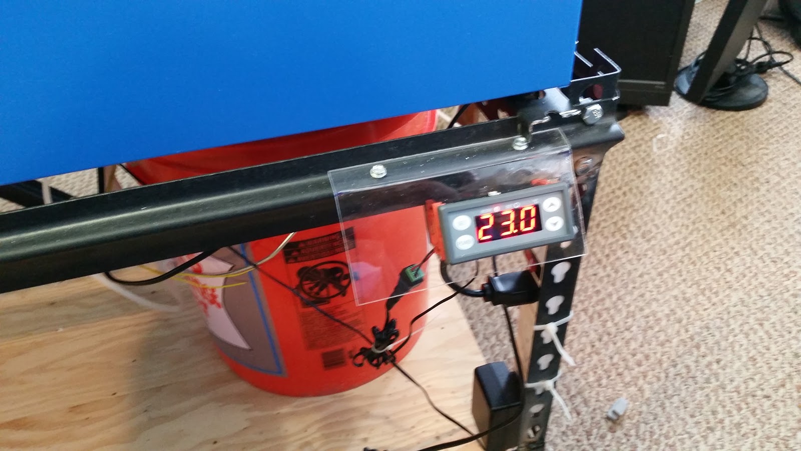
This device's relay contacts (NC) is also wired in series with the interlock circuit and will disable the laser from firing if the temperature is to high or low. The probe is put into the bucket near the output or the flow sensor.
See Build Schematics  for details.

This controller can be set up to produce an audible alarm outside of its set-points. (See the manual). I mounted it on thr front of the machine but plans are to move it up to the control panel later. The unit requires 12VDC so an additional supply is needed. Before I installed the 12V supply in my conversion I used a 12V brick plugged into a power strip. 


Enjoy and comment
Maker Don