INSTRUCTIONS:

Check out the new MoBeam posts! To find K40 conversion information use the "INDEX", "SEARCH" or "LABELS" sections in the sidebar.

Thursday, December 16, 2021

MoBeam: Configurable bed

 Bed Design

The bed in the MoBeam is unique in that it allows for:
  • Objects to be placed below the focal plane
  • An adjustable focal frame that can be adjusted up/down from the focal plane. This focal frame is mounted to the base frame
The adjustable focal frame can have these inserts:
  • Nothing
  • Solid surface
  • Angle inserts that can be placed anywhere in the frame

Below the Focal Point

In this scenario, the entire base frame is adjusted up/down with bolts in the corner of the base frame.


Adjustable Frame @Focal Plane

In this scenario the adjustable focal frame can have:

Solid bed

 
Open bed with angled slats to facilitate cutting and airflow

 
Enjoy and please comment,
Don

MoBeam: Laser Head Mounting

 The Laser Head

I have a habit of overcomplicating my first prototypes and the laser head in the MoBeam is no exception. This is all part of the learning process and the willingness to "iterate".

The original design included a plastic cage to allow the laser head to slide up and down fastened with thumbscrews. https://donsthings.blogspot.com/2021/09/l7x-vertical-adjustment-slide.html

As I climbed up the learning curve I found these things that helped me get to a simpler solution
  • You can purchase a Laser Diode head mounting bracket 
  • A refrigeration capillary tube is a good choice for routing air assist 
  • The head and the air assist must be adjustable for both G8 and G2 Lenses
    • The FL for the G8 is 30mm.
    • The FL for the G2 lens is 10mm

A Simpler Head Mounting Design

This design replaces my original vertical adjustment approach 

New
Old


 Air Assist

An air assist nozzle was implemented using a piece of capillary tube that I salvaged from my HVAC replacement last summer. You can get tubing here: https://amzn.to/3q55qMa

The tubing is held to the laser module with two magnets that hold it to a piece of sheet metal when in operation. The sheet metal is screwed to the face of the laser module. This setup allows the nozzle to be adjusted up/down when moving the laser module for different lenses.

Existing mounting plates

These plates came with the unit. The black plate is used to cover the belt and carriage wheel access holes giving a flat surface for the new adapter plate to mount.

New Adapter Plate

The height adjustment plate is mounted to the face of this Lexan plate from the back. This plate is mounted to the carriage via 15 mm cap head screws & the supplied thumbscrews. These fastners sandwich the existing and new mounting plates together and to the carriage. 

Height Adjustment Plate

This Laser Module Mount Holder Spring Clamp assembly was purchased from NEJE. This assembly holds the edges of the laser module with a spring-loaded clamp. The laser module can be adjusted vertically by loosening the cap screw sliding the module up/down and then re-tightening the screw.
My process to adjust for FL is to place a precision block under the lens, loosen the clamp, slide the head until it interposes the block, and then tighten the clamp. This approach is simple and accurate. I plan to use two lenses, a G8 and G2 dictating that the head be able to be adjusted a delta of 20mm.


Optical Sheild

The optical shield design originally included a disk that also served as a means to rotate the lens for focus. https://donsthings.blogspot.com/2021/10/mobeam-focus-with-safety.html
Testing revealed that the lens can be adjusted one time for fine focus and then the entire head moved to achieve final focus. This is especially true of the 30mm (F8) lens. 
After measuring and calculating the size of the shield I decided to attach it below the laser module with two magnets. This way the head can be adjusted down inside the shield for the short FL lense leaving the optical shield in one place.

It is important to note that MoBeam is designed so that the target material is always below the focal plane. Therefore the head only needs to be moved for lens changes. 


Watch it in action!!!


Enjoy and please comment,
Don

MoBeam: Baseframe build update #1


Build Notes #1

MoBeam is intended to be a shop tool like a router or jigsaw. To that end, I focused on its mobility with the ability to engrave on finished woodworks of various types and sizes including vessels turned on my wood lathe. I traded off automation for simplicity and at the expense of more manual adjustments.

A fundamental concept was to leave the laser diode module at a fixed focus and instead move the entire assembly and/or a focal plane insert up-down as needed to get the target in focus. Sound crazy?

The laser focus is set at 30mm [G8 lens] up from the bottom surface of the base frame. The entire assy or alternately just the focal frame is then adjusted up/down based on the thickness of the target. In a way setting up MoBeam is similar to setting the bit depth on a wood router.


The laser module gantry assembly is mounted on a piece of 3/4" plywood into which an opening is cut. This opening is left open or alternately accommodates a honeycomb bed [the one I bought for my K40 and never used]. The entire assemblies surface is adjustable with 4 1/4-20 bolts

Very thick or odd shaped targets:

When left open the target is placed on the bench under MObeam and the entire assy is adjusted up/down with 4 legs until the target is parallel to the bottom of the base plate.


Small Flat Targets That Fit on the Cutting Bed [in the focal frame]

When the focal frame is used it is mounted in the opening and 4 screws allow it to be adjusted until the target’s [laying on the bed] surface is the correct distance from the laser's lens. The assy is mounted into the base plate with 4 thumbscrews. Focus adjustments are made with a gauge block.


Large Flat Work
If a larger flat material needs to be engraved [front of a chest] the gantry assy can be dismounted from the base frame by removing 4 [thumb] screws from the side plates.

The gantry assy is placed flat on top of the target and no additional adjustment is needed.


Laser Module Adjustments
The only time the laser module needs adjusting is if the lens is changed and then it is simply located to the surface with a gauge block.


Cheap n Dirty Build Highlights
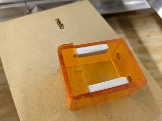
Views showing the adjustments for the base frame and focal frame insert.


Detailed views of the focal plane adjustment mechanism.
Yes I know, I cringed when I started this design …
However this assy worked better than I expected. Then again I took a lot of care to ensure the holding bracket and the bed mounts were perfectly aligned. The adjustments [one screw at a time] were not as clunky and painstaking as I thought and it did not bind until I adjusted only one screw a ridiculous amount relative to the others.


Known problems:

The nutserts in the lift bracket don’t like the thin AL angle and tend to come loose, a PEM nut would be better.
The honeycomb bed is not really flat [never realized that] a thin perforated metal plate would be better.

Known Improvements/Adds & Before You Ask

  • Tilt and lift interlocks on laser power
  • Air evacuation. I am working on a plenum that slides under the baseframe.
  • Filter: considering a canister filter design that uses the evac fan salvaged from my HVAC replacement
  • Completed: Thumbscrews and cap head on adjustment screws to prevent striping and the need for hand tools.
  • Protective cover and handle for storage.
  • The use of metal vs wood for the base plate would help with fastening and dimensional predictability but beam reflections would need to be considered.
  • Taller Acrylic side plates for better stability.


Enjoy and please comment,
Don