Background
Interlocks are an important feature of your K40. Although simple in principle I found them annoying to wire.I created a breakout board to make this process easier.
The K40-S BUILD INDEX with schematics
Donate:
Please consider donating (button to the right of this post).
Your donations help fund additional research, tools and parts that I will return to the community as information and how-to's.
How to add interlocks to your K40
 |
| Interlocks cut from the main schematics |
Note: J11 in the schematic above connects to the ARMED LED (on the control panel) through a resistor to 5V. See the main schematic.
WARNING: in a previous version there was an error caused by the Interlock Open LED that allows the laser to fire without the "Laser Switch" being activated. Make sure that your LED is wired like above and not directly across the "+P, Gnd like it was before..
Below is a sketch of the interlock circuit. You should not put anything but switch contacts in series with the interlock loop. The P+ or WP connection is connected to the cathode of an opto-couplers LED and that pin must be ground to allow proper current to the op-ocouplers input diode.
If you want to add an optional ALARM led you can add it outside the circuit as shown. The LED must be connected into the circuit exactly as the sketch below shows.
In normal operation the LED reminds me that laser is enabled. When the LPS won't fire I find it useful to see if that ALARM led is lit. If not I know the interlock circuit is open.
 |
| Equivalent interlock circuit showing optional ALARM led |
The interlock LED now indicates that the laser is "ARMED", I like that better anyway :).

BOM
The board parts are simple:- Radio Shack or other vector board. Pick a size that fits your application
- Screw terminals: https://www.amazon.com/gp/product/B00GWF65WY/ref=oh_aui_search_detailpage?ie=UTF8&psc=1
- A panel mounted LED: https://www.amazon.com/gp/product/B00P3FMGP4/ref=oh_aui_search_detailpage?ie=UTF8&psc=1
- A resistor of the appropriate size for your LED.
Mine is 5 ports. I suggest adding as many ports as you can to use for further expansion. You can plug a shorting wire into any ports that you are not using.
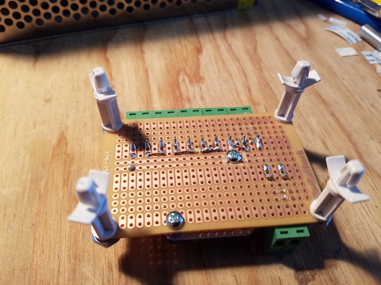
Wiring
This board through J75 connects to the LPS "Laser Switch" loop for your laser supply type.J11 goes to a led + resistor on the front panel. It tells you if any interlocks are open. This was added after the following pictures were taken.
To add an interlock you create a simple two-wire assy's that comes from each interlock switch to the breakout which uses screw terminals.
Note: You can ignore the middleman board I mounted it there for convenience and then later removed it. If you are not mounting the MM board your board can be smaller.


Update
After it was all wired I realized that the Middleman board and interlock board have no connections with each other and no functional relationship.
Moving the Middleman board off the interlock board and into the Smoothie cabinet, cleaned up the wiring.
 |
| Interlock board with Middleman removed |
 |
| Middleman moved to left wall of cabinet |
Interlock Switches
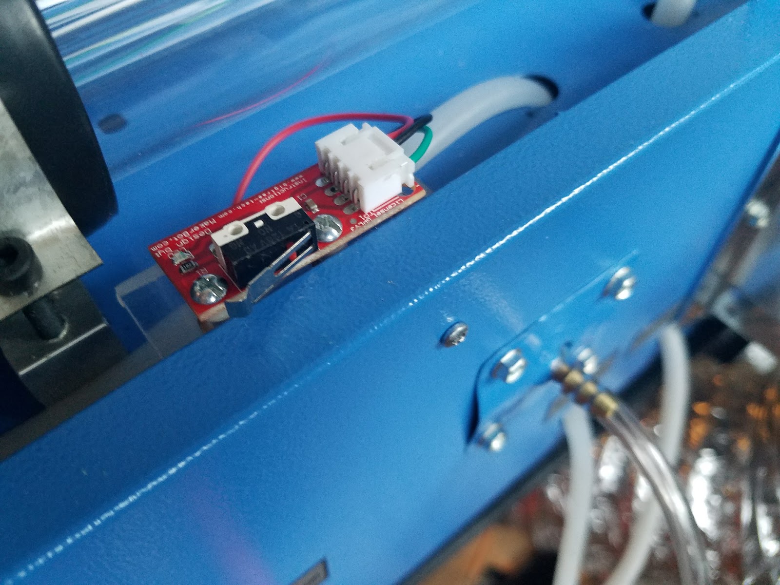
I found some switch assemblies that make the mounting of interlocks and there interconnect easier and with no soldering requirements.Purchase:Interlock switch assy.
Although this assy was designed for endstops it also works great for interlock switches.
Switch Assembly Schematic

Main Compartment Interlock Mounting
The main compartment can easily be protected by adding the interlock switch to the lower right of the middle partitions surface, no bracket is needed. An interposing block is affixed just above it in the cover. When the cover closes it energizes the switch and enables the laser.
I used a piece of wood that was 26 mm x 26 mm x 25.4 mm but you may have to custom cut one depending on where your switch is mounted on the partition. I drilled holes for the sheet metal screws right were the partition bends.
Make sure to put insulating spacers under the board so that the lands do not short against the case.
Make sure to put insulating spacers under the board so that the lands do not short against the case.
Note; that's my old soldered version hanging in the bay waiting to be removed.


Laser Compartment Switch Brackets
I designed the bracket for my laser tube compartment out of acrylic so it can be laser cut. Normally I bend brackets but in this case, due to the small size of the bracket, I glued it. The design's slotted holes allow for adjustment of the switch PCB and mounts on the inside of the outer wall of the laser tube compartment. I mounted it near a hole that is about 11" from the left edge of the cabinet. This gave me easy wiring access to the electronics compartment and kept the switch well away from the Anode of the laser avoiding any electrical noise or arc problems. The bracket is mounted with two sheet metal screws after drilling through holes in the face of the cabinets sheet metal. The sheet metal screws were threaded into the plastic before assembly and I found that one hole held the bracket solid, two holes are provided. The tricky bit is to get the bracket holes in the right place on the cabinet. I held the bracket up to the surface and marked them. You will find at the place there is two layers of sheet metal to drill through. Be careful and don't poke through and hit the tube.


This arrangement also allows a magnet to be placed on the ledge to defeat the switch.
I don't recommend defeating interlocks, make sure you wear eye protection if you do!
 |
| Defeat magnet |
 |
| Cover interpose block |
The SU Design
The design fileEnjoy, and please comment
Make Don
No comments:
Post a Comment