Background
This post captures the many K40 PS configurations that I am/have worked on.
READ THIS POST if you want to know about how to digitally control a K40 LPS:
I need Laser Power Supply's (LPS) (dead or alive) to test:
If anyone has a LPS schematic or a blown LPS that we can use to better understand its interface please contact me at: don_kleinschnitz@hotmail.com or comment below.
Donate:
If anyone has a LPS schematic or a blown LPS that we can use to better understand its interface please contact me at: don_kleinschnitz@hotmail.com or comment below.
Donate:
Donate:
Please consider donating (button to the right of this post).
Your donations help fund additional research, tools and parts that I will return to the community as information.
Please consider donating (button to the right of this post).
Your donations help fund additional research, tools and parts that I will return to the community as information.
Reverse engineering Information:
From Scott Marshall on G+:
This is the manufacturers page there's specs and such there, minimal, but some info.
http://en.jnmydy.com/products_list.html
http://en.jnmydy.com/comcontent_detail/&FrontComContent_list01-1285720952066ContId=4&comContentId=4&comp_stats=comp-FrontComContent_list01-1285720952066.html
Inputs P+ and K+ directly drive these optos:http://www.everlight.com/file/ProductFile/EL817.pdf
Driving this PWM Controller by good old Texas Instruments
http://www.ti.com/lit/ds/symlink/tl494.pdf
Inputs are speced at 5v, but look to work on 3,3v (show 3v logic High)
It's pretty conventional switching supply stuff from there. The Hv circuit seems to be a flyback running at about 440hz (awful low) with a tripler output.
300W 11kv nominal 4-20ma (26kv insulation breakdown)
From Scott Marshall on G+:
This is the manufacturers page there's specs and such there, minimal, but some info.
http://en.jnmydy.com/products_list.html
http://en.jnmydy.com/comcontent_detail/&FrontComContent_list01-1285720952066ContId=4&comContentId=4&comp_stats=comp-FrontComContent_list01-1285720952066.htmlhttp://en.jnmydy.com/products_list.html
Inputs P+ and K+ directly drive these optos:http://www.everlight.com/file/ProductFile/EL817.pdf
Driving this PWM Controller by good old Texas Instruments
http://www.ti.com/lit/ds/symlink/tl494.pdf
Inputs are speced at 5v, but look to work on 3,3v (show 3v logic High)
It's pretty conventional switching supply stuff from there. The Hv circuit seems to be a flyback running at about 440hz (awful low) with a tripler output.
300W 11kv nominal 4-20ma (26kv insulation breakdown)
Measurements
Shown in "[approx value]" are the measurements taken from my machine as a help in troubleshooting.
These measurements are approx and your actual readings may vary.
However if they are way off that may be an indication your have a problem.
BTW: wire colors also match my machine but yours may be different.
AC Power Connector
Not always in this order
- -L (cathode of laser) [0 ohms to frame and to cathode of laser]
- FG (frame ground, directly connected to frame)[0 ohms to frame]
- AC (one side of main power)*
- AC (other side of main AC power)*
DC Power Connectors:
The DC Power connector on the LPS typically contains these signals:
[* ] = measurements with DC connector disconnected
- 5VDC (Yellow) [*5VDC to frame & gnd]
- GND (Black) [*0 ohms to frame]
- 24VDC (Green) [*24VDC to gnd and frame]
- L (Pink) (the M2 Nano LO pin connects to this pin in stock K40's) [*4VDC]
The DC Power connector on the LPS typically contains these signals:
[* ] = measurements with DC connector disconnected
[* ] = measurements with DC connector disconnected
- 5VDC (Yellow) [*5VDC to frame & gnd]
- GND (Black) [*0 ohms to frame]
- 24VDC (Green) [*24VDC to gnd and frame]
- L (Pink) (the M2 Nano LO pin connects to this pin in stock K40's) [*4VDC]
DC output capacity specs:
- 24v@ 1 amp
- 5V @1 amp
General LPS specs for GWWG LPS from ebay:
 |
| Taken from ebay site |
Understanding K40 Laser Power Supply Configurations
To effectively test, repair, replace and convert K40 LPS it is necessary to know that kind of supply you have.
This section attempts to identify and categorize the LPS I have encountered. There are two parts to identifying the LPS:
- Physical Configuration
- Control Schema
An example configuration might be: GGGR-A. The notation is explained below.
Power Supply Physical Configurations:
Key to my physical configuration labelling
First Letter: color of AC power connector
Second Letter: color of control connectors
Third Letter: color of DC power connector
Fourth Letter: color of Power LED
Physical Configuration GWWG
Label on back of my LPS supply, I got to it with a video borescope :)
Ebay: MYJG40 (first time I have seen one like mine for sale)
Label on back of my LPS supply, I got to it with a video borescope :)
Ebay: MYJG40 (first time I have seen one like mine for sale)
Ebay: MYJG40 (first time I have seen one like mine for sale)
MYJG40W [S/N: 2015090481]
 |
Mine looks like this (I think this type is out of production): |
Physical Configuration GGGR
- LPS part #: MYJG40W [S/N: 2015090481]
- Example Suppliers website: http://www.ebay.com/itm/40W-Power-Supply-CO2-Laser-Engraver-Cuttier-Machine-110V-220V-Switch-green-Sale-/231550508351?hash=item35e97c5d3f:g:lqwAAOSwuMFUcpR

Laser Power Supply (LPS) Control Interface Schema's
K40 LPS typically have either 1 green 6 pin connector or 3 white connectors for control (located between the AC and DC connectors. In all cases some combination of their signals perform the same basic functions of:
The basic way these signals are used is shown in the sketch below.
- laser enable
- laser
- analog power control.
The basic way these signals are used is shown in the sketch below.
 |
| Showing the interface equivalent circuit. |
Control Schema Labels A-C
I arbitrarily labeled the two types of control interfaces "A" - "C" to simplify the documentation. Type "A" LPS Control Schema
This is a common K40 supply and is usually physical configuration GWWR or GWWG.This schema uses 3 separate white connectors in the order below from left to right.
Laser Switch (enable)
- P+ Laser Switch [**4.28VDC]
- P- gnd return for Laser Switch [0 ohms to frame]
Test Switch ("FIRE")
- K+: Test switch [**4.28 VDC]
- K-: gnd return for laser [0 ohms to frame]
Current regulation
- Ground: signal ground [0V to frame]
- IN: laser current control 0-5VDC [**not sure, likely floating]***
- 5VDC: 5V power [** 5.02 VDC]
Note: the "Current Regulation" pot is connected across these three signals with the center tap connected to IN.
*** you can partially test "IN" by measuring the resistance across IN to gnd while turning the Current Regulation POT on the panel. The resistance should vary with pot position.
** voltage measured with connectors removed
*** you can partially test "IN" by measuring the resistance across IN to gnd while turning the Current Regulation POT on the panel. The resistance should vary with pot position.
Type "B" LPS control interface
These supplies often have black cases and sometimes have only the control and AC connectors. They usually do not provide DC power.
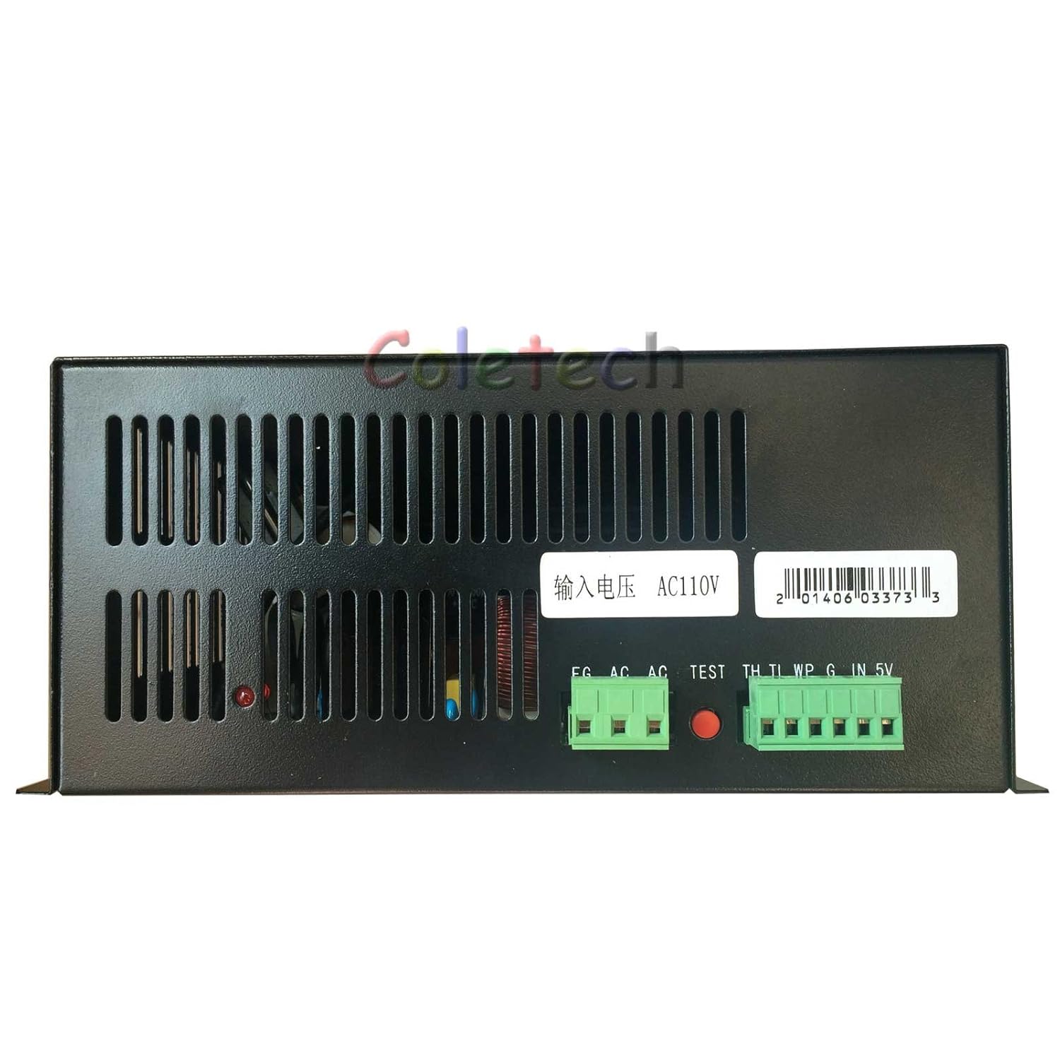
Terminal Definition as follows:
| TH | Input Signal | On-Off laser control,TH≥3V, emitting laser; TL≤0.3V, no laser. |
| TL | Input Signal | On-Off laser control,TH≥3V, no laser; TL≤0.3V, emitting laser |
| WP | Input Signal | On-Off laser control,TH≥3V, no laser; TL≤0.3V, emitting laser |
| G | GND | This foot must be connected well with the laser machine shell and the ground of control board. |
| IN | Input Signal | The control of laser power: Both 0-5V analog signal and 5V PWM signal can control the laser power. |
| 5V | Output Power | Output 5V, the maximum output current is 20mA. |
Note: WP = water protection, this is an interlock loop for the water pump.
Type "C" LPS Control Interface
I think this is the configuration that ships with newer K40's.


Type D Control Schema
Same schema as a Type A but a "D" signal replaces the "P" and works the same.

Special LPS Wiring
 |
| Special wiring for this supply, note part # at top of drawing |
Converting From One Supply Type to Another
 |
| Conversion of GGGG-C to GWWR-D |
LPS Related Album
Enjoy and comment
Maker Don
Have a question on the current limiter for the 5V in. If you are still doing this stuff, could you drop me a line? I don't normally use this forum.
ReplyDeleteDave V at country_cutter@aol.com
I am replacing Power supply in K40 - using same control board that came with unit
ReplyDeleteold supply has D+ D- with a jumper
I see D+ D- is mapped to Laser switch
would I just jump the laser switch?
totally out of my comfort zone have no one I know thats any help
any direction you can give me much appreciated
To replace the power supply digital GWWR with analog power supply it is only necessary to invert k- with k+ and G with P from the above scheme . Tested and working on laser 40w .
ReplyDeleteHi, you explained all this great. I'm a new laser user so I'm not sure I've found a way to upgrade a new power supply? I currently have a MYJG40W which is not ok and I ordered a new CLOUDRAY HY-T50. How now to connect type c to type b, please can you draw how to connect?
ReplyDeleteA very awesome blog post. We are really grateful for your blog post. You will find a lot of approaches after visiting your post electrical services
ReplyDeleteA very awesome blog post. We are really grateful for your blog post. You will find a lot of approaches after visiting your post Kuala Lumpur Malaysia!
ReplyDelete