INSTRUCTIONS:

Check out the new MoBeam posts! To find K40 conversion information use the "INDEX", "SEARCH" or "LABELS" sections in the sidebar.

Sunday, October 31, 2021

MoBeam: Grbl Startup

Grbl Newbie Stash 

Being new to Grbl this is a stash of information that I will reference for converting my stock controller to the MiniGrbl.

Grbl 1.1 Laser Mode


Enjoy,

Comments are always welcome. 

Please, consider using the donate button on the sidebar if you found this post valuable!

Don

Saturday, October 30, 2021

MoBeam: VigoWorks Setup & Operation

VigoWorks

Documentation

The documentation describes the functions but not in enough detail to understand how they impact engraving and cutting quality.

Software_manual

Notes:

  • Many modes of the software are single-threaded. Ensure that windows are closed and you exit active modes before trying to make settings changes. Sometimes the interface does not intuitively tell you to change modes.
  • I do not see any way to engrave and cut at the same time. There is no way to mark image features as cut lines.
  • There is a way to design text string but there is no image or vector editing. 
  • You supposedly can upload Gcode and Images.
  • I have experienced intermittent crashes and the controller needed to be power cycled.
  • No way to add stuff to the gallery?

The Effects of Settings on Imaging 

I plan to update this until which time I change to LightBurn.

Offline Imaging

Default file on SD card

  • Name: sd_default.nc
  • One file is allowed and must be named with .nc extension
  • Verify: Uploaded and overwritten from VigoWorks?

----------
Enjoy,

Comments are always welcome.

Please, consider using the donate button on the sidebar if you found this post valuable!

Don


MoBeam: Positional Accuracy

Movement Scale

I found that the X & Y movement was 1/2 of what it should be. In other words when I told it to move 50mm it moved 25. I found this using the arrow keys in VigoWorks.

I changed the steps/mm from 80 to 160.
The preset value when this model is selected is 80.
Yet the manual says 160 in a picture of the settings.
I set the steps to 160 and it now scales correctly.
I am concluding the presets are wrong!

Settings in manual 

Settings when L7X model is selected

Settings I changed

----------
Enjoy,

Comments are always welcome.

Please, consider using the donate button on the sidebar if you found this post valuable!
Don

MoBeam: Software/Firmware Updates

Software Update

VigoWorks 3.25_2110203

When I opened VigoWorks it asked if I wanted to update to which I said yes.
It simply took me to a download site, it did not directly update the code. I assume this is because VigoWorks is a .exe, not an installed program. After download and extraction, the .exe ran without error. now I have two versions on my desktop. 

  • New version: VigoWorks_v3.25.exe

Firmware Update

The extracted file from the download site also contained a firmware file and tools.
  • New Firmware: Firmware_for_328p_v3.12_20211023
On the Settings tab and under Model there is a checkbox to upgrade firmware.
Checking this box opens a file dialog and allows the selection of a .hex file.
Select the .hex file that was downloaded
There is a ribbon at the top of this dialog that shows upload progress.
Unfortunately for me, this FAILS and I have no idea why??

OTA Update?

I tried updating the firmware via WIFI and IT WORKED. I say that because it no longer asks me if I want it updated and I think I saw some LEDs blinking strangely. BTW it seemed to just update automagically without asking me to select a file. Where did it get the file from? Does VigoWorks only update OTA and do you have to use the flash tools if you are serially connected?

Upload Tools

There is also an upload tool under "Driver_And_FwUploadTools" but I am confident how to use it and do not want to brick my controller.

Using the Upload Tools

Trials of a Poorly Supported Controller

I do not know if I need to upgrade the firmware nor what the new version does. [I wonder if they fixed the Grbl problem and I can now use Lightburn].

I cannot find any support help nor documented release change information regarding the firmware update ..... just an upload site and good luck with that.

This is what happens when your controller is not properly supported and has incomplete documentation

----------
Enjoy,

Comments are always welcome.

Please, consider using the donate button on the sidebar if you found this post valuable!

Don

MoBeam: Laser Focus

Laser Module in MOBeam

Is this module actually a NEJE module

If so which one?
  • 30820
  • 30610

Focus

Mistake in the manual???? Yes my focal point is 30mm.

If you assume the VG-L7X manual had the wrong units for focus, i.e CM vs MM.

Then I have a G8 lens in my unit? Is this a coincidence?

The smallest beam spot also explains why the dot looks rectangular (laser diodes do not operate in TEM00).

However, at the focal point, the intense area of the beam is round.

https://laserpointerforums.com/threads/there-is-something-wrong-with-my-beam-spot.59400/

Finding The Focal Point

Focusing Techniques


4% is low power setting used for focus

The Empirically Derived MoBeam Focal Distance

Focus Using a USB Microscope

There are multiple videos on the use of a USB microscope to safely look at the output of the diode and adjust the focus. I decided that I would start finding my focal point by using this method.

Test Setup

I used a USB microscope purchased* from Amazon. 
* I am very happy with this unit's price and performance. https://donsthings.blogspot.com/2021/10/usb-microscope-review.html
  • Make a target by painting a substrate with flat black paint. I used a round steel medallion. A black surface makes it easier to see the most intense part of the beam. 
  • Put on your laser safety glasses
  • In Vigoworks turn on the "weak beam"
  • Place the microscope on its stand in front of the laser module focussed on the beam.

Adjustment

Watching the beam on the microscope:
  1. Adjust the entire module up/down to get the smallest round spot.
  2. With the module fixed in position adjust the lens until the smallest round spot is achieved. 
When you adjust either the module or the lens you will note that the beam changes from a round spot to a rectangular one as it goes in and out of focus.

In this video, you can see how I went about finding the focal point.

These tests show that the focal point is indeed 30mm.

Depth of Focus Measurement

TBD

Focusing For Cutting vs Engraving


----------
Enjoy,

Comments are always welcome.

Please, consider using the donate button on the sidebar if you found this post valuable!

Don

MoBeam: Text Engraving

Engraving Text

Aluminum Techniques

Engraving Painted Aluminum Vigotec VG-L7 20W Laser Engraver

  • Speed: 750 - 1250 mm/min
  • Power: 90-95%
  • 13 dots/mm
  • Pause: 45ms
Post clean with alcohol & cotton ball

From YouTube Video

From the Manual

In the right parameter control area of the software,
  • Select Binary-Line engraving mode.
  • Adjust the size of the engraving picture.
  • Adjust the line engraving speed value to 3000,
  • Laser power value to 90%,
  • Line or point density DPM value to 6

1st Lettering Experiment #1

The first attempt at engraving letters was somewhat successful.
Wood engraved easily and at very low power.
Painted Plastic and Steel are also etched at an expected higher power but there are visible horizontal scan patterns for which I do not know the source. I suspect the dots/inch setting has something to do with this pattern in that the scans are not adequately overlapped.

Wood


No horizontal patterns

  • Speed: ?? mm/min
  • Power: 4%
  • 5 dots/mm
  • Pause: 50 ms

Painted Plastic


Horizontal patterns, scan or settings error?

Painted Steel


Horizontal patterns, scan or settings error?


  • Speed: ??? mm/min
  • Power: 80%
  • 5 dots/mm
  • Pause: 50ms

Test #2

I decided to try this same test [on the blackened steel] using the same settings the YouTube video above used. The results were dramatically better. There is a lot more that needs to be understood about how these engraving settings work. 
Note both the settings and USB image overlayed in the screenshot below.


Calculate the resolution @ 5dots/mm:

5 dots/mm x 25.4 mm/inch = 127 dots/inch [very low resolution]
Line spacing = 1/127 = .007 inches

Calculate the resolution @ 13dots/mm:

13 dots/mm x 25.4 mm/inch = 330 dots/inch [more like a laser printers resolution]
Line spacing = 1/330 = .003.

The combination of higher resolution and power resulted in the ablated areas being more "clean". That is, there is more overlap of the beam from scan to scan.

If I guessed the optics characteristics correctly the laser beam is at its smallest 0.0030315 x 0.00511811. This suggests that at the lower resolution 127 dots/in the beam scans do not overlap by .002-.004" which would clearly be visible.

----------
Enjoy,

Comments are always welcome.

Please, consider using the donate button on the sidebar if you found this post valuable!

Don

Sunday, October 17, 2021

MoBeam: Focus on Safety

 Safety

Clearly, the MoBeam needs to have safety considerations included in the design. 
The core design goal is for this machine to be portable able to lay on top of various size targets for the purpose of engraving on them. 

Safety considerations include:
  • Protection from the beam in normal operation
  • Protection from the beam if the machine is lifted off the surface
  • Interlocks on any covers that open horizontally placed relative to the laser.

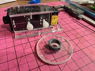
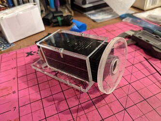
Head-Sheild

My current approach is to use a light shield under the diode head made of filter material. The body of the machine may be made from clear acrylic. I do not think the body needs to use filtered materials when combined with the head-shield.

Caution: I have not tested this concept. It seems logical that the placement of the shield [close to the surface] would make a dangerous reflection unlikely. Also, this approach
is being used by others that I judge to know what they are doing.

JTech 

JTech is one of the best sources I have found on Laser Diode safety, engraving, cutting, and technique.

Sheild Material

I plan to replace the prototype shield [disk under head] in the picture with this material as soon as I get the specifications for focus discovered. 
These are:
  • Practical FL
  • Practical DOF

250nm to 520nm Laser Shielding – 12″ x 12″

The shield may also serve as the focal adjuster.
PXL_20210916_121149841

PXL_20210916_121027926

Lift Interlocks

To further make this safe I also plan to have the means to turn off the laser if the machine is lifted off the surface. You could also accomplish this with a full enclosure but I am trying to make MoBeam capable of laying on top of various thicknesses of materials, mostly wood. Therefore the bottom of mine will be open.


----------

Enjoy,
Comments are always welcome.
Please, consider using the donate button on the sidebar if you found this post valuable!