INSTRUCTIONS:

Check out the new MoBeam posts! To find K40 conversion information use the "INDEX", "SEARCH" or "LABELS" sections in the sidebar.
Showing posts with label K40. Show all posts

Tuesday, January 12, 2021

Connecting and splicing the HV connection

Installing a new tube

If you own a laser machine, sooner or later you will have to install a new tube. There are various methods for doing this and various opinions on what is the right way. There is always more than one right way but the methods outlined here I feel are the simplest verified methods I know of.

DANGER WILL ROBINSON!

This is 20,000 volts. Unless you are experienced with High Voltage (HV) power, you may not realize this does not act like any other electric circuit you have ever been exposed to. Its behavior is unpredictable and it can KILL YOU!

The red wire used to provide power to the anode is a special HV wire that is capable of insulating this high of voltage. NO other common wire is capable of insulating this high of voltage. This high voltage has no problem penetrating electrical tape as well as many other common insulating materials.

If you do not use HV connection and fabrication techniques and materials your machine may be unsafe and also may prematurely damage your LPS.

Installation Overview

Tubes usually come with bare pins or pigtails installed. In rare cases, it may have a High Voltage connector. A method from below can be chosen that best suits your needs, skills, and part availability. 

The Cathode Connection

For the negative, you can use any type of splice you get from the home store. I would solder or crimp on the splice and finish with heat shrink. This wire must stay away from the HV (red) lead. It should be routed directly back to the LPS pin -L, usually the leftmost pin and connection on the LPS.

CAUTION: do not connect the cathode connection to L which is on the rightmost LPS pin and connector.

The Anode Connection

Before we talk about the anode connection it’s important to realize that 20,000-volt connections do not act like the kinds of connections we normally use. What we normally know as “insulating materials” do not adequately insulate at this voltage. Other fabrication and environmental conditions, such as moisture, dirt, dust, and sharp points in the assembly, can cause HV leak problems 

  • HV easily arcs through conventional connection and insulation methods
  • 20,000 volts can easily arc 2" to a grounded surface
  • 20,000 volts creates corona and corona tracks from sharp points
  • 20,000 can create conductive tracks in dirty, dusty materials, etc when not properly insulated
  • 20,000 volts at 30ma is capable of killing you and or damaging most any electrical/electronic circuit …

For connecting the anode wire your options are:

  • Add a HV connector ***** inline with the existing HV cable and the new tube's pigtail. This makes it easy to change the tube in the future. HV connector must be installed correctly. I seal the ends with high dielectric constant silicon RTV **.
  • Solder the HV pigtail end directly into the LPS (like is it currently connected) which requires you to get access to the inside of the LPS and unsolder the wire and solder in the new pigtail. This only works if the pigtail is long enough to reach your LPS. This connection is the best as there are no discontinuities in the HV wiring. However, it is the most involved method and it requires access to the HVPS internals.
  • Make your own splice using plastic/silicon tubing and HV resistant silicon.
    • Slide tube over the open end of the pigtail. The bigger the diameter tube the better. Silicon tubing generally can have a smaller diameter than PVC plastic tubing.*** The key is to get enough thickness of silicon to adequately insulate the HV from its surrounding. The tube should be sized such that it will extend at least 1" from either side of the joint's edge of insulation.
    • Join the pigtail to the existing LPS HV lead by twisting them like this:
    • You can leave the joint like this but I like to solder it. If you solder it, use bulb soldering****. Soldering or not, ensure there are no sharp points of wire sticking up.
    • Apply a liberal amount of the RTV over and around the joint.
    • Slide the tube over the joint and RTV. You want the RTV to fill the tubing with no air pockets.
    • If the tubing is not full of RTV add more into each end of the tubing until you get an adequate squeeze-out. Pretty is not important here, filling the tube with silicon is!
    • Let the splice cure for 24 hrs before applying power

Stuff to make your own splice:

** Blue RTV. You may be able to get this at auto supply stores, Walmart or https://amzn.to/3qc9xob

*** You can find silicon tubing on Amazon I recommend 1/2 or larger. I have also used larger diameter 1/2-3/4 PVC tubing as an alternate material. It's the total thickness of silicon that does the insulation work.

****Ball Soldering: https://www.spellmanhv.com/en/Technical-Resources/FAQs/Technology-Terminology/What-is-Ball-Soldering

***** HV Connector: https://amzn.to/2K8rVPn


Enjoy and please comment,

Don

Monday, February 4, 2019

K40 Laser Power Control Characterization

Laser Power as a Function of Operator Controls

Recently +Ned Hill replaced his digital control panel with an analog one.
In the process he was thorough enough to take some measurements of the digital panels effect on laser power. Since Ned replaced the laser and the LPS this data may well describe an ideal K40 machine.
  • %PWM, 
  • Control Voltage (on the LPS-IN pin)
  • Laser Current 
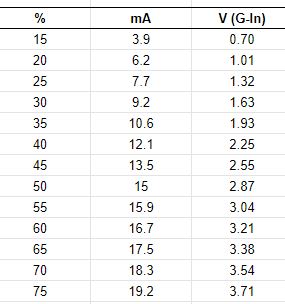
The +Ned Hill post and associated data are here and copied below for reference:

Tube%20power%20percent%20table 

This data shows the important relationship between the digital panels setting [%] and its relationship to the control voltage [V(G-IN)] on the LPS-IN pin and in turn the lasers power level. The LPS-IN signal results in the laser current seen at the ma meter [mA]. 

Observations About the Data

Multiple Linear Regression models can be constructed that more show us these relationships in mathematical form. Perhaps these simple math equations can help us predict the K40's performance and therefore more accurately choose settings.

I ran linear regressions on the above data to see if rational models could be derived to describe the laser powers behavior.

How Digital Panel Setting Control Laser Current Behavior

A regression was calculated using column 1 and 2 in the data above. The below equations represent a model of the relationship between panel settings and the resulting laser current.

equation 1: Tube Current = Digital Panel % * .2784 {R^2 = 0.996}**
equation 2: Digital Panel % = Tube Current/.2784

You can use these equations to estimate the laser current for a given digital panel setting or alternately estimate what panel settings will result in a what laser current.

The **R^2 value and this graph shows that the equations above should be pretty good predictors of laser current for a given panel setting. 

Note: the equation above predicts that at 100% Neds laser should draw approx 28ma of current.

How The Pot*** Setting Controls Laser Current Behavior

A regression was calculated using column 3 and 2 in the data above. The below equations represent a model of the relationship between panel settings and the resulting laser current.

equation 3: Tube Current = Control Voltage * 5.24 {R^2= .999]**
equation 4: Control Voltage = Tube Current/5.24

You can use these equations to estimate the laser current for a given pot setting or alternately estimate what pot settings will result in a what laser current.

The **R^2 value and this graph shows that the equations above should be pretty good predictors of laser current for a given panel setting. 

Note: The equation above predicts that Neds laser should draw 26.2 ma with the IN voltage at 5vdc.

*** the pot is sometimes called "Current Regulation" on stock machines that come with a pot.

How Do I Know What the Pot Setting Is?

Good question! The equation above uses "Control Voltage" as one of the variables so how do you know that value? Install a DVM on the POT. It tells you the control voltage it presents at the LPS-IN pin.

To use this schema read or set the pot until the DVM reads the voltage [control voltage] you calculated using equation 4 above. 

Your Mileage May Vary?

Statistical models are based on empirical data like that given in this post can be in error in a few ways, garbage-in-garbage out. 
+Ned Hills data is likely "IDEAL" since it was taken with a new tube and LPS. As such it should be a great reference as to what a K40 machine can do.

Here are some sources of error (assuming I did the math right):
  • Your LPS is weaker than Neds new one
  • Your Digital panel is defective 
  • The 5v supply used to drive the LPS-IN pin is an incorrect value
  • Your tube is weaker than Neds new one
  • Your mileage may vary

Local vs Programmatic Control

When firing the laser from the control panel the power is entirely controlled by the Digital Panel or Pot Settings. Therefore the equations above apply. 

However when under programmatic control from a PWM signal on the LPS-L pin the lasers power control is more complex. Its power is the product of the controller PWM % and the control voltage on the LPS-IN pin.

Using the Digital Panel To Set Laser Power

Laser current = (PgmPwr/100) * (DigitalPanel * .2784)

whereas: 
  • PgmPwr = the power setting in the control software as a percent
  • DigitalPanel = the setting on a K40 digital panel as a percent

Simple Example:

- DigitalPanel is set to 100%
- Lightburn power setting is 50%

     Laser current = (50/100) * (100*.2784)
     Laser Current = .5 * 27.8
     Laser Current = 13.9 ma

With the above settings when you push the test button you should see the meter read 27.8 ma
When running from program control you will run much less than 27.8 since the static value set by the digital panel will be reduced by any program setting less than 100%. 

Using The POT To Set Laser Power

Laser current = (PgmPwr/100) * (ControlVoltage* 5.24)

whereas: 
  • PgmPwr = the power setting in the control software as a percent
  • ControlVoltage = the voltage on the LPS-IN pin as set by the pot

Simple Example:

- Pot is fully on i.e. LPS-IN = 5vdc
- Lightburn power setting is 50%

     Laser current = (50/100) * (5*5.24)
     Laser Current = .5 * 26.2
     Laser Current = 13.1 ma

Is This Academic Knowledge?

If you expect your system to act exactly like +Ned Hill's then yes this may just be interesting information about Ned's machine. If however you value this information as a model of an ideal K40 machines laser power control behavior more value can be extracted. 

Ideas I have for using this knowledge are:

After taking a few settings *** on a machine you may;
  • See how close it performs to ideal
  • Create a model to match your actual machine by factoring the ideal model
  • Use the model to aid in choosing operational power settings
  • Attain a gauge to track your machines performance as it wears out
  • Troubleshoot laser control problems without electrocuting yourself  
*** take 3 measurements of laser current vs control voltage or digital panel settings.

Donate?

If this post helped you solve a problem, saved you time or was otherwise useful consider donating. Use the link in the upper right of the site.
Donations fund some of the expense of tools and materials for my shop and lab so I can bring you more content like this. 

Also let me know if there is other content you would like to see me explore!
_____

Thanks and please comment
Don