INSTRUCTIONS:

Check out the new MoBeam posts! To find K40 conversion information use the "INDEX", "SEARCH" or "LABELS" sections in the sidebar.
Showing posts with label K40 Laser Power Meter. Show all posts

Monday, February 4, 2019

K40 Laser Power Control Characterization

Laser Power as a Function of Operator Controls

Recently +Ned Hill replaced his digital control panel with an analog one.
In the process he was thorough enough to take some measurements of the digital panels effect on laser power. Since Ned replaced the laser and the LPS this data may well describe an ideal K40 machine.
  • %PWM, 
  • Control Voltage (on the LPS-IN pin)
  • Laser Current 
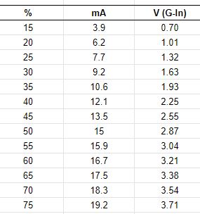
The +Ned Hill post and associated data are here and copied below for reference:

Tube%20power%20percent%20table 

This data shows the important relationship between the digital panels setting [%] and its relationship to the control voltage [V(G-IN)] on the LPS-IN pin and in turn the lasers power level. The LPS-IN signal results in the laser current seen at the ma meter [mA]. 

Observations About the Data

Multiple Linear Regression models can be constructed that more show us these relationships in mathematical form. Perhaps these simple math equations can help us predict the K40's performance and therefore more accurately choose settings.

I ran linear regressions on the above data to see if rational models could be derived to describe the laser powers behavior.

How Digital Panel Setting Control Laser Current Behavior

A regression was calculated using column 1 and 2 in the data above. The below equations represent a model of the relationship between panel settings and the resulting laser current.

equation 1: Tube Current = Digital Panel % * .2784 {R^2 = 0.996}**
equation 2: Digital Panel % = Tube Current/.2784

You can use these equations to estimate the laser current for a given digital panel setting or alternately estimate what panel settings will result in a what laser current.

The **R^2 value and this graph shows that the equations above should be pretty good predictors of laser current for a given panel setting. 

Note: the equation above predicts that at 100% Neds laser should draw approx 28ma of current.

How The Pot*** Setting Controls Laser Current Behavior

A regression was calculated using column 3 and 2 in the data above. The below equations represent a model of the relationship between panel settings and the resulting laser current.

equation 3: Tube Current = Control Voltage * 5.24 {R^2= .999]**
equation 4: Control Voltage = Tube Current/5.24

You can use these equations to estimate the laser current for a given pot setting or alternately estimate what pot settings will result in a what laser current.

The **R^2 value and this graph shows that the equations above should be pretty good predictors of laser current for a given panel setting. 

Note: The equation above predicts that Neds laser should draw 26.2 ma with the IN voltage at 5vdc.

*** the pot is sometimes called "Current Regulation" on stock machines that come with a pot.

How Do I Know What the Pot Setting Is?

Good question! The equation above uses "Control Voltage" as one of the variables so how do you know that value? Install a DVM on the POT. It tells you the control voltage it presents at the LPS-IN pin.

To use this schema read or set the pot until the DVM reads the voltage [control voltage] you calculated using equation 4 above. 

Your Mileage May Vary?

Statistical models are based on empirical data like that given in this post can be in error in a few ways, garbage-in-garbage out. 
+Ned Hills data is likely "IDEAL" since it was taken with a new tube and LPS. As such it should be a great reference as to what a K40 machine can do.

Here are some sources of error (assuming I did the math right):
  • Your LPS is weaker than Neds new one
  • Your Digital panel is defective 
  • The 5v supply used to drive the LPS-IN pin is an incorrect value
  • Your tube is weaker than Neds new one
  • Your mileage may vary

Local vs Programmatic Control

When firing the laser from the control panel the power is entirely controlled by the Digital Panel or Pot Settings. Therefore the equations above apply. 

However when under programmatic control from a PWM signal on the LPS-L pin the lasers power control is more complex. Its power is the product of the controller PWM % and the control voltage on the LPS-IN pin.

Using the Digital Panel To Set Laser Power

Laser current = (PgmPwr/100) * (DigitalPanel * .2784)

whereas: 
  • PgmPwr = the power setting in the control software as a percent
  • DigitalPanel = the setting on a K40 digital panel as a percent

Simple Example:

- DigitalPanel is set to 100%
- Lightburn power setting is 50%

     Laser current = (50/100) * (100*.2784)
     Laser Current = .5 * 27.8
     Laser Current = 13.9 ma

With the above settings when you push the test button you should see the meter read 27.8 ma
When running from program control you will run much less than 27.8 since the static value set by the digital panel will be reduced by any program setting less than 100%. 

Using The POT To Set Laser Power

Laser current = (PgmPwr/100) * (ControlVoltage* 5.24)

whereas: 
  • PgmPwr = the power setting in the control software as a percent
  • ControlVoltage = the voltage on the LPS-IN pin as set by the pot

Simple Example:

- Pot is fully on i.e. LPS-IN = 5vdc
- Lightburn power setting is 50%

     Laser current = (50/100) * (5*5.24)
     Laser Current = .5 * 26.2
     Laser Current = 13.1 ma

Is This Academic Knowledge?

If you expect your system to act exactly like +Ned Hill's then yes this may just be interesting information about Ned's machine. If however you value this information as a model of an ideal K40 machines laser power control behavior more value can be extracted. 

Ideas I have for using this knowledge are:

After taking a few settings *** on a machine you may;
  • See how close it performs to ideal
  • Create a model to match your actual machine by factoring the ideal model
  • Use the model to aid in choosing operational power settings
  • Attain a gauge to track your machines performance as it wears out
  • Troubleshoot laser control problems without electrocuting yourself  
*** take 3 measurements of laser current vs control voltage or digital panel settings.

Donate?

If this post helped you solve a problem, saved you time or was otherwise useful consider donating. Use the link in the upper right of the site.
Donations fund some of the expense of tools and materials for my shop and lab so I can bring you more content like this. 

Also let me know if there is other content you would like to see me explore!
_____

Thanks and please comment
Don

Replacing the K40's Digital Panel with an Analog one

Why replace the panel?

It is not uncommon for the K40's digital panel to fail and more and more users are realizing the value of having a pot for control and an analog meter read laser current.

The digital panel

Understanding the k40 digital control panel

Adding an analog meter.

Adding-analog-milliamp-meter-to-k40.html

Converting the Digital Panel to Analog

Recently +Ned Hill had a LPS failure and tube replacement and decided to replace the digital panel and do a C3D upgrade.
We thought posting the conversion would be useful to others in the community

Schematic

I added a conversion diagram to the existing schematics I had for the digital panel.
It is located on the tab "Convrt 2 Analog".
https://www.digikey.com/schemeit/project/k40-powerled-v30-PM4QJBO303GG/


Conversion Instructions:

These conversion instructions are for supplies with all GREEN connectors. I can add the equivalent for other supplies upon request.

This conversion entails replacing the digital panel with an analog equivalent. The new analog panel has a switch, momentary push-button, pot, and digital voltmeter. The harness that goes from the LPS to the digital panel can be reused with the addition of two wires. These instructions refer back to the schematic.

-Build and mount the new analog panel (blue area)
-Remove the connector from the digital panel (orange area)
-Cut off the connector and strip back the wires
-Reconnect the 4x digital panel wires as shown in the schematic to the new panel (blue area)
-You will have to add 2x wires to the harness the G and the 5V

Note: this schematic also shows an installed pot and an associated control voltage DVM

Extracted from the schematic

Pictures From +Ned Hill Conversion

Supply Connections


Purchase Links

Please buy your parts using my affiliate links. It costs you nothing and it helps fund my activities. I defined a kit for this project which contains all the parts and links to amazon.
The entire kit is here and points you to these parts on Amazon.


Contributors

Thanks to +Ned Hill for his contribution to this post.

Donate?

If this post helped you solve a problem, saved you time or was otherwise useful consider donating using the link in the upper right of the site.
Donations fund some of the expense of tools and materials for my shop and lab so I can bring you more content.

----

Thanks, and please comment,
Don

Sunday, April 9, 2017

Adding an Analog Milliamp Meter to a K40

Instructions for Adding an Analog Meter to a K40


Some vintages of K40's now have digital meters and pots. Some users find then sufficient and convenient others have found that having more information about the position of the pot and an analog representation of the laser tubes current to be advantageous.  

While you are adding this meter to your K40 you may also consider adding a high resolution pot and/or a pot position indicator: 
Thanks, to +Bob Buechler for testing out these instructions, doing the drawings and reporting on the results in this post.

Donate:

Please consider donating (button to the right of this post).
Your donations help fund additional research, tools and parts that I will return to the community as information.
For other information on the K40-S build use the  K40-S BUILD INDEX with schematics

Installing the Analog Meter

Summary of the installation.

The analog meter is going to be installed in series with the wire that routes from the lasers cathode to the -L connection on the Laser Power Supply (LPS). 
[the -L connection is the leftmost pin on the leftmost connector on most LPS's]

Here is a simplified wiring drawing of the installation, courtesy of +Bob Buechler:
Before

Installation

You will need the following materials

  • New Meter Note: this meter is larger than used in the stock K40
  • Wire, as needed for your installation
  • Heat shrink tubing, as needed for your installation
  • Ring tongues, as needed for the meter you choose
  • Terminal Pin  and crimper

You will need the following tools:

  • Wire cutters
  • Soldering iron & or crimp-er to match the terminals you are using
  • Pliers or small wrench for tightening the meter nuts

Meter Mechanical Installation

  • Pick an appropriate place to install your meter, cut hole(s) as needed and install

Meter Wiring

  1. 1. Pre-check:
    1.  Verify that with the "Laser Switch" enabled, when you push the test function the laser fires.
    2. Power down and unplug the mains from your machine
  2. Find the wire that connects to the cathode (the end the laser light comes out of) end of the laser tube. Often its a black or green wire. 
  3. Trace that wire to its other end which should be connected to ground (L-) at the LPS. Note: never not ground the cathode or the (-) side of the meter directly to the frame. The lasers current must return to the LPS itself on pin -L. 
  4. Find the lasers ground port on the LPS. Its usually called L-, its the leftmost connection on the leftmost connector. Do not confuse this with the L that is on the rightmost connector with the DC voltages.
    L- on LPS with all green connectors

    L- on LPS with green and white connectors
  5. Remove the existing wire from L- and verify with an ohmmeter that that the LPS pin (L-) is connected to the FG pin on the LPS and that both of those pins (L- & FG) are connected to the frame of the machine. There should be close to 0 resistance to ground (frame) on these pins. Note: this is a good time to test that there is 0 ohms to GND at the frame pin on the mains connector.
  6. We want to reroute the existing wiring (that went from the tubes cathode to the LPS) to the (+) side of the meter. Do such by pulling the L- end of the wire that connects to LPS out of the harness enough to reroute it to the + side of the newly installed meters terminals. Note: Unless absolutely necessary do NOT disconnect the wire from the cathode as that is difficult to replace. When this step is finished the wire that previously was routed from the lasers cathode to the L- is now rerouted to the + side of the meter.
  7. Connect the wire of step #6 to the meters + terminal with an appropriate terminating terminal. Usually the meter has threaded studs with nuts and washers. I recommend using a ring tongue terminal soldered to the wire. See parts list above.
  8. It is common for the meters terminals not to be marked. If not marked start by connecting this wire to the left terminal of the meter (looking from the back), its a guess!
  9. Get a new piece of wire that is long enough to route back to the LPS (L-) pin from the (-) of the meter. 
    1. Use the same size or larger wire (yes it matters) and the same color if possible (colors do not matter but will be easier to trace later). 
    2. Connect this wire from the meters (-) terminal to the L- of the LPS.  
    3. Terminate the meter end with a ring tongue like step #7. For the LPS end use a crimped pin of the correct wire size. If you do not have the ability to crimp a pin at least strip back and tin the wire with solder. Insert the wire into the L- terminal and tighten securely.
  10. After insuring that you have not shorted anything with shards of wire etc prepare to return power to the machine. As a rule I vacuum my machine in the area I have been working with a crevice tool. Be careful not to create a static charge.
  11. Return power to the machine with your hand on the switch in case of smoke. No smoke? Then proceed.
  12. Turn the power adjustment pot (or digital control) to about 1/3 or less of its range. In case the meter is in backward we do not want to stress it. 
  13. To test the meter enable the laser [Laser Switch] and then push the [Laser Switch] while watching for movement in the meters needle. The meter should read the lasers current and you are done.
  14. If no movement is noticeable on the meter these things could be wrong:
    1. An error in the wiring, recheck using the steps above.
    2. The meter is in backward. Swap the wires on the back of the meter and return to step 10.
    3. The laser is not firing, check to see if the tube ionizes?
    4. If you cannot get it to work post a picture of all of the above connections and wiring with my G+ address +Don Kleinschnitz in the Laser Engraving 

Links on G+


"Ideally you want to cut the wire in a way that the meter can physically be placed in series with it leaving the cathode and the LPS end terminations alone. Just putting ring tongues where you cut it to connect the the meter. i.e The meter is placed in series with the current wire.

If the wire is not long enough cut the cathode wire long enough to reach the meter and put a ring tongue on it and connect it to + of the meter. Get another wire that is long enough to reach the LPS and put a ring tongue on it connected to the - side of the meter. Put a pin terminal on the LPS end.

Don't have a pin terminal and crimp-er? Alternatively tin the wire with a liberal amount of solder and insert and screw that into the LPS terminal.

If you want to keep the pin terminal you can splice it and a section of wire to a longer piece just insure you solder properly and cover it with shrink wrap."

Soldering Ring Tongues

I solder these type terminals because I have had problems with crimps corroding and/or vibrating loose. Theory is that if you crimp correctly this will not happen however soldering insures it does not.

Prepare the wire:

Strip the wire back far enough so that the bare end inserts fully into the barrel to its end

Heat-shrink:

Cut and slide over the wire a piece of heat-shrink that will cover the barrel of the terminal after soldering. The plastic cover may or may not come off or loose from heating. Most of the time I remove the plastic before starting.

Solder

Put the ring tongue on a heat restive surface or in a clamp. I lay mine flat on a piece of 600 grit sandpaper (the surface is heat resistant). Insert the wire through the barrel. Press with the iron on the ring tongue side of the terminal and heat while applying solder until the barrel of the terminal fills up. Depending on the size it may take a fair amount of heat. Don't put so much solder on it that it flows around the ring as that will impede attaching it to screws.

Finish

Clean flux from the terminal and slide the heat shrink up over the barrel and shrink it over the plastic if its still there. Sometimes the plastic falls off or needs to be cut off.

Some say this is overkill because its a pain to do but I have never had one fail over years of use.


Enjoy and comment!
Don