INSTRUCTIONS:

Check out the new MoBeam posts! To find K40 conversion information use the "INDEX", "SEARCH" or "LABELS" sections in the sidebar.
Showing posts with label K40 Cooling. Show all posts

Thursday, February 1, 2018

Enhanced K40 Temperature Monitoring

Updated K40 Temperature Sensing

I have one point of temperature monitoring  in my K40, water. I recently moved my K40 to the garage shop and decided to get rid of all the hacks and partially complete conversions. Temperature monitoring was one of those on the agenda to be completed. Mostly the temperature controller needed to be remounted but while I was at it I decided to add some more gauges .....

Donate:

Please consider donating (button to the right of this post).
Your donations help fund additional research, tools and parts that I will return to the community as information.
For other information on the K40-S build use the  K40-S BUILD INDEX with schematics

More Temperature Monitoring

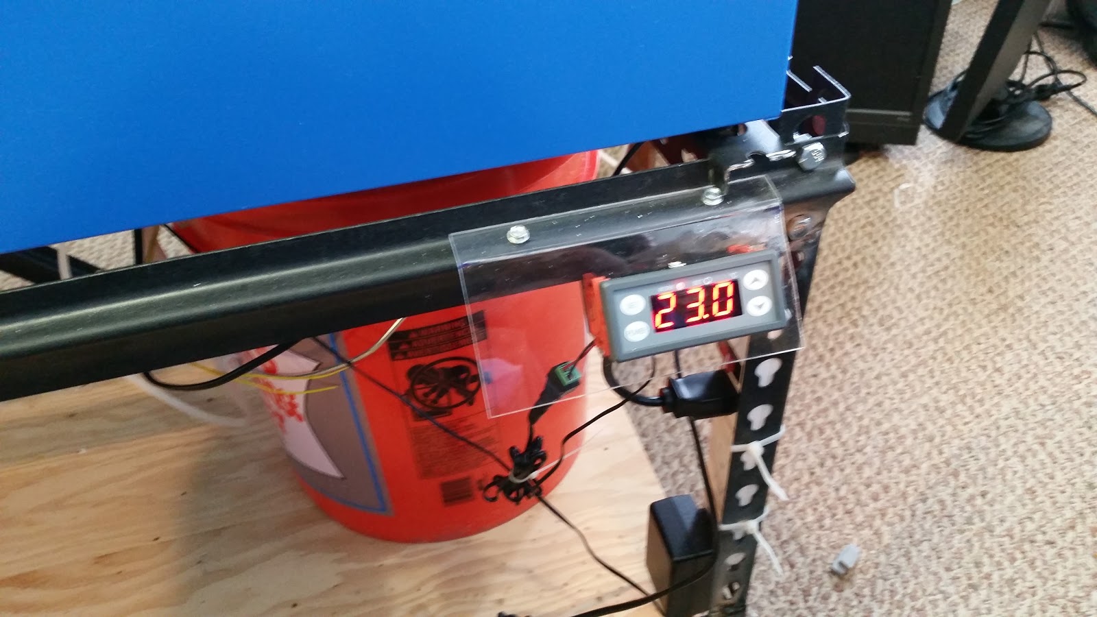
I already had a sensor in the water bucket connected to a controller that I had mounted lazily on the frame of the K40's kart.
This controller will alarm at an over temperature and since its relay is in the K40's interlock circuit it will shut off the laser.

This is the controller.  If its no longer available check for other similar ones. It needs to have an alarm function that opens the interlock when the temp setpoint it exceeded.


Gauge Mounting

The current controller/gauges were mounted on the upper part of the K40 control panel. It would have been nice if all these gauges were the same type. Then again their difference in appearance makes their varying purpose more obvious. In any case I went with function and cost over aesthetics.


One of my next projects will be to engrave acrylic labels for these. In the mean time their functions are:
  • Upper left: Cabinet temp
  • Upper right: Coolant temp
  • Lower left: Laser tube temp
  • Lower right: Laser power level

Gauge Installation

After removing the current control panel and then the hinged cover I used my nibbler to cut the holes for the new gauges. That nibbler is a must have "maker" tool!


Cabinet Temperature

This sensor is more of an experiment than anything. The sensor is located on the gantry near the air assist nozzle and is wired into the K40 interlock circuit. Its purpose it to sense a fire in the cabinet and turn the laser off. I have no way of testing or proving if this will work but I figured considering the damage a fire can do it was worth the effort and money! The idea is that a fire will melt the sensor and open the circuit. The controller will alarm if the sensor is disconnected and open the interlock circuit..... I hope.
I can imagine many cases where this may not work:
  • The head is not near the fire
  • The sensor shorts from the fire
  • The cabinet self destructs before the sensor sees it
I used this 2 stage controller which is overkill but can be used if I ever build in a water cooler. 
I plan to set this alarm on this sensor to the lowest practical operating temperature I can.


Laser Tube Temperature

A sensor was tie wrapped to the laser tube's glass and routed to the gauge. This sensor monitors only and is not wired into the K40 interlock circuit. I hope to learn more about the temperature in the lasers cabinet and eventually plan to add air to that cavity. This gauge required a spacer since the panel sheet metal was to thin for the mounting tabs to firmly hold the meter in place.


As an FYI you can see the new water sensor and air assist connections at the bottom of the photo.

Laser Power Meter

The last meter in this set is the digital voltmeter that is connected to the LPS's control pot. I had to add a frame and filter to the naked small digital voltmeter so that it had a better mounting, is more readable and somewhat nicer looking.
I added gel filter material between the display and the face plate to get the display to be more readable.

Old Power Setting Meter ... dangling

Mounting and Wiring

Meter mounting. Note the adapters on the upper meters.


Enjoy, comments and suggestions expected :)
Don


Wednesday, January 31, 2018

Improved K40 Cooling Circuit

The Mobile Converted K40

K40 Cooling Circuit

My cooling system has been mostly a hack of tubes, pipes, switches and interlocks. Improving it has  for some time taken a back seat to other K40 conversion activities. I recently moved my K40 to the garage shop and decided to get rid of all the hacks and partially complete conversions. The cooling circuit was one of those on the agenda to be rebuilt.

These things bothered me about the current setup:
  • The flow switch was in series with the water circuit likely reducing the coolants flow.
  • The wiring was a hack and any time I had to troubleshoot the sensor wiring I had to solder and un-solder stuff. 
  • I had to stand on my head to get to the water bucket and its aritfacts.
  • I had no visual way to tell if water was flowing other than the interlocks were not open.
  • And lastly and the most annoying was the need to clear air bubbles from the laser tube at every water change.
This post details the rebuild of my cooling water and sensor systems circuits.

Donate:

Please consider donating (button to the right of this post).
Your donations help fund additional research, tools and parts that I will return to the community as information.
For other information on the K40-S build use the  K40-S BUILD INDEX with schematics

Clearing Bubbles & Water Replacement

After each water change I had bubbles. I tried every form of water conditioning additives and patiently running the pump for days... nothing got rid of the bubbles. Some info on water conditioning and additives is located under Water bubble treatment

In my case I had to lift the left side of the machine very high, more than 45 degrees and tilt the back toward the front until the bubbles would exit the laser through the hooked cooling exit of the laser tube. Not something you want to do by yourself and not a healthy for a device that has marginal optical stability anyway. 

The Solution

As is often the case, the solution ended up to be simple. Just don't ever drain all the water out of the system and break the cooling circuit! 

Add A Spigot

I added a drain to the bucket. The solution is to drain all but the last 1-2 inches of water out the drain. Since the pumped water exits a pipe that is in a fixed position below this level, the coolant circuit is never broken and therefore bubbles will not form when the circuit is refilled. Actually the laser tube is never refilled, the bucket is. See the circuit diagram.

Yes, a disadvantage is that some coolant remains in the system after a change. I judge that amount of old coolant to be acceptable and over time I will prove it by keeping track of my waters conductivity.

The drain spigot came from Wallmart. I found it where the buckets are sold. Drill a 1" hole in the bucket about 2" up from the bottom and hand thread the spigot into the hole with a bead of "Plumbers Goo" around the flange. You can also screw a flange (its a garden thread) on the inside if you want it to be more secure. I recommend the white Wallmart buckets as you can see the water level easily.


The New Cooling Circuit Diagram


Water & Electrical Circuit Diagram

Shutoff Valves V1-V2


Just in case.... I have a backup approach to the bubble problem. I added two shutoff valves in series with the input (V1) and the output (V2) of the lasers water circuit. The idea is to shut these both off and then remove the tubing from the pump to the valve. Drain and refill the bucket. Start the pump and while water is exiting push it onto V1, this essentially bleeds the input. Then turn on V1 and V2 and the cooling circuit is back to normal with no bubbles.
Valves V1 and V2 are also useful to isolate the cooling system from the bucket if you need to remove it. 

The valves I found are made for fuel shutoffs in mowers. I chose them because they are inexpensive but also because they have a pretty low restriction. Most other valves narrow to a very small hole and or are very large.

Pump

Although a higher capacity pump is likely in my future I am using a Harbor Freight pump for now. I noticed that the laser tube has a pretty high impedance to flow and I am not sure that a higher capacity pump is worth the money. For now, I focused on keeping the diameter of all the tubing and fittings as large as possible. Be careful because much of the available 1/4 tubing fittings dramatically restrict flow.

Flow Switch

I did not like the way my flow switch operated.  It is in serial with the water flow. I worry about the restrictions. I decided to change to a T (parallel) connected diaphragm switch. This one came from Light Objects. It mounted conveniently under the lid, tapped (with a T) off the pump's output. 

I found out that the switch will not work if you put it on the output side of the system after the laser tube. There is not enough back pressure to fill the leg of the T and subsequently activate the switch's diaphragm. However, it works fine on its lowest setting when put directly at the pump's output. 

Note: the screw on the backside of the diaphragm plunger is not an adjustment it is just a fastener.

I was concerned that if I placed the switch at the input there was a failure mode such that if the line between the pump and the laser opened the sensor would still see water flow and not open the interlocks. Not to worry when the line opens the backpressure decreases and the interlock opens.

The T and other piping were different sizes so I had to play with a combination of silicon tubing slipped over the fitting and some 1/4" copper tubing to make the fittings work. Tie wraps and on non-silicon materials "Plumbers Goop" secured them. Your approach and success may vary!
Thanks for the switch suggestion +Tech Bravo !


Pressure switch under the lid

Lid Assembly

I wanted the lid and its components to be easily and modularly removed from the system and the bucket. Therefore the electrical connections for the water temperature sensor and the pressure switch were wired into a 4 pin Aviation connector

This is the first time I have used these. They are perfect for this kind of builds as they are rugged, soldered, and keyed. A cable with one on each end now connects from the bucket to the back panel of the K40. 

An output tube was made from 1/4 copper with a flange to mount it to the lid. With this setup the K40 can be totally disconnected from the lid of the bucket and the bucket lid can be disconnected from the bucket. 

The output tube was affixed to the lid with a copper flange. Cut a copper fitting (1/2") down one side and then flatten it out to make a plate. Drill a 1/4" hole and solder the pipe at the right level. Screw that plate to the plastic lid with self-tapping screws.

Tie wrap the water temp sensor to the output tube so that the sensor is near the opening to get the best reading.


Output tube mounting flange


Lid assembly

Top of lid

Bottom of lid

 Water Flow

I decided to put a visual water flow sensor into the output of the coolant circuit. This flow meter was mounted to an acrylic bracket and mounted to the K40's mobile frame so it was out of the way but still visible. I found out the hard way these meters work best in the orientation as shown and they must be purged of bubbles. Since we do not plan to break the coolant circuit you will only have to bleed the bubbles once. I found you can do that just by tilting this assembly clockwise.


Funny I just noticed that V2 is on the wrong side of the meter!

Meter glued into an acrylic bracket


 The video below shows the water flow meter in action. It also shows the new air-assist flow meter [thanks +Ned Hill ] that I also installed, but that is another post yet to come.


Enjoy, comments, suggestions, and corrections expected:
Don


Wednesday, May 17, 2017

K40 Coolant Flow and Termperature Sensing

Background

Note: much of this approach has been replaced by: Improved k40 cooling circuit

The K40 laser needs coolant that is maintained at the correct temperature to prevent damage to the tube. It is not uncommon to forget to turn on a coolant pump or to have a pump or water system failure while running the K40. 
Sensors are easy to install in a converted K40 and the protection of the laser tuber certainly warrants the installation annoyance and cost of a flow sensor.

It is also desirable to know the temperature of the water and the tube. This post also outlines the installation of an inexpensive water temp sensor and control.

Donate

Please consider donating (button to the right of this post).
Your donations help fund additional research, tools and parts that I will return to the community as information.
For other information on the K40-S build use the  K40-S BUILD INDEX with schematics

Flow Sensor

Sensor

The loss of cooling water will certainly cause damage to the laser and the laser power system. Every system should have a flow sensor plumbed in series with the pump and the lasers cooling jacket.
The sensor that I use is:

This sensor needs to be installed on the output side of the laser. I made a hanger to hold it upright on the side of a 5 gal bucket. This way it insures that water is flowing out of the laser and it can detect any leaks from the pumps output to the sensors input.


Electrical connections;

The flow sensor is connected in series with the interlock circuit and in effect stops the laser from firing if there is no flow. 
See Build Schematics  for full machine details

If you for some reason do not want to add a sensor at least insure that the pump comes on with the machine. You can simply plug the pump and machine into the same power strip and turn them both on at the same time.

The End of My Tube Fell Off!

If you did not install a water sensor then at some point the pump will not be on, due to failure or  simply forgetting to turn it on, and the tube will overheat.

If the tube overheats the water jacket on the end of the tube can de-laminate and fall off.

Apparently if you are careful to keep it off the optical output area of the jacket you can use EPOXY it back on. I would surmise that high temp epoxy would be best.

GLUE IT BACK ON!

Temperature Monitoring

The laser must stay within its coolant operating range if it is to operate consistently and reliably. The cooler the laser is kept the more power it will be capable of. The power capacity of the laser will change with temperature therefore it is important to monitor the water temperature and prevent the laser from operating is the temp gets to high.
Install temperature monitoring electronics such as:

This device's relay contacts (NC) is also wired in series with the interlock circuit and will disable the laser from firing if the temperature is to high or low. The probe is put into the bucket near the output or the flow sensor.
See Build Schematics  for details.

This controller can be set up to produce an audible alarm outside of its set-points. (See the manual). I mounted it on thr front of the machine but plans are to move it up to the control panel later. The unit requires 12VDC so an additional supply is needed. Before I installed the 12V supply in my conversion I used a 12V brick plugged into a power strip. 


Enjoy and comment
Maker Don

K40 Coolant Pumps

Background

Information about common water pumps and coolant flow specifications

Donate:

Please consider donating (button to the right of this post).
Your donations help fund additional research, tools and parts that I will return to the community as information.
For other information on the K40-S build use the  K40-S BUILD INDEX with schematics

Water Pumps

From +Scott Marshall :"When all is well, the stock system should fill a 1 gallon jug about 1/2 full in 60 seconds. About 1/2 gpm or 2 Lpm. .................. the Little Giant PE-1 is a good quality replacement pump which is just right for the k40 and available worldwide."


Enjoy and comment
Maker Don