INSTRUCTIONS:

Check out the new MoBeam posts! To find K40 conversion information use the "INDEX", "SEARCH" or "LABELS" sections in the sidebar.
Showing posts with label MoBeam. Show all posts

Tuesday, November 2, 2021

Laser Diode Lens Specifications


There are 4 common types of diode laser lenses:

  • 3 element
  • G2 (short focal) (cutting)
  • G7 (similar to 3 element lens)
  • G8 (Used in VG-L7x)

The G8 has these specs:

  • Optimal focal range: 30-100 mm
  • EFL: 8mm
  • NA: .2
  • Best focal range 70-75 mm
  • Smallest laser beam spot: 77 x 130 microns (0.0030315 x 0.00511811")


Briefly about a 3 element laser lens

A 3 element collimating lens w/ AR coating for 405nm – 465nm. It has M9/P0.5 threads that will work with a lot of standard diode housings available. This lens is good for correcting laser beams for long ranges.

Briefly about a G2 laser lens

This lens is the best choice for short ranges, as in an engraving machine. For long ranges please consider 2 or 3 element lenses.

Briefly about a G7 laser lens

The G7 is a second-best high pass single lens but it won’t increase the beam divergence as the G2 does. The G7 has a long focal length just like a 3-elements lens. It’s a well-balanced lens that has the advantage of 3 element lens (very good divergence) and G2 (in terms of power).

Briefly about a G8 glass collimation lens.

Broadband AR Coating 400nm-700nm
This lens is a long focal length single-element glass lens with a broadband AR coating. It has a 90% pass efficiency which is amazing for a longer focal length lens. It does an amazing job of cleaning up stray light around the projected spot with many common diodes caused by the small amounts of uncollimated light escaping the lasing cavity reflecting off things like the edge of the emitter, walls of the module or inner walls of the lens barrel. Like the G2 lens or countless other similar lenses being sold as G-2’s, it creates a reduced spot size while maintaining a 90% pass efficiency compared to the 96% pass efficiency of a G2 lens.

Comparison of Lens Performance

3-element lens (cleanest beam profile, best for low power lasers)

The 3-element lens has a long focal length, low divergence, and clean beam profile but it has a significant output loss.
Advantage Tight laser beam with the cleanest beam profile
Downsides 84% efficiency (1W diode = 700mw using this lens)

G2 lens (best for power)

The G2 is a single lens enabling the maximum true power of the laser diode for rapid close-range burning and engraving.
Advantage 94% efficiency, reduces the beam aperture
Downsides Increase the beam divergence (thickness) and the beam profile

G7 lens(Balanced Multi-Purpose Perfection)

This lens is a cross between the divergence and the power lens. With the G7, the beam divergence won’t increase as it does with the G2 and you will still get very close power of the laser diode.
Advantage 91% efficiency, long focal length and increases beam aperture.

Saturday, October 30, 2021

MoBeam: VigoWorks Setup & Operation

VigoWorks

Documentation

The documentation describes the functions but not in enough detail to understand how they impact engraving and cutting quality.

Software_manual

Notes:

  • Many modes of the software are single-threaded. Ensure that windows are closed and you exit active modes before trying to make settings changes. Sometimes the interface does not intuitively tell you to change modes.
  • I do not see any way to engrave and cut at the same time. There is no way to mark image features as cut lines.
  • There is a way to design text string but there is no image or vector editing. 
  • You supposedly can upload Gcode and Images.
  • I have experienced intermittent crashes and the controller needed to be power cycled.
  • No way to add stuff to the gallery?

The Effects of Settings on Imaging 

I plan to update this until which time I change to LightBurn.

Offline Imaging

Default file on SD card

  • Name: sd_default.nc
  • One file is allowed and must be named with .nc extension
  • Verify: Uploaded and overwritten from VigoWorks?

----------
Enjoy,

Comments are always welcome.

Please, consider using the donate button on the sidebar if you found this post valuable!

Don


MoBeam: Positional Accuracy

Movement Scale

I found that the X & Y movement was 1/2 of what it should be. In other words when I told it to move 50mm it moved 25. I found this using the arrow keys in VigoWorks.

I changed the steps/mm from 80 to 160.
The preset value when this model is selected is 80.
Yet the manual says 160 in a picture of the settings.
I set the steps to 160 and it now scales correctly.
I am concluding the presets are wrong!

Settings in manual 

Settings when L7X model is selected

Settings I changed

----------
Enjoy,

Comments are always welcome.

Please, consider using the donate button on the sidebar if you found this post valuable!
Don

MoBeam: Software/Firmware Updates

Software Update

VigoWorks 3.25_2110203

When I opened VigoWorks it asked if I wanted to update to which I said yes.
It simply took me to a download site, it did not directly update the code. I assume this is because VigoWorks is a .exe, not an installed program. After download and extraction, the .exe ran without error. now I have two versions on my desktop. 

  • New version: VigoWorks_v3.25.exe

Firmware Update

The extracted file from the download site also contained a firmware file and tools.
  • New Firmware: Firmware_for_328p_v3.12_20211023
On the Settings tab and under Model there is a checkbox to upgrade firmware.
Checking this box opens a file dialog and allows the selection of a .hex file.
Select the .hex file that was downloaded
There is a ribbon at the top of this dialog that shows upload progress.
Unfortunately for me, this FAILS and I have no idea why??

OTA Update?

I tried updating the firmware via WIFI and IT WORKED. I say that because it no longer asks me if I want it updated and I think I saw some LEDs blinking strangely. BTW it seemed to just update automagically without asking me to select a file. Where did it get the file from? Does VigoWorks only update OTA and do you have to use the flash tools if you are serially connected?

Upload Tools

There is also an upload tool under "Driver_And_FwUploadTools" but I am confident how to use it and do not want to brick my controller.

Using the Upload Tools

Trials of a Poorly Supported Controller

I do not know if I need to upgrade the firmware nor what the new version does. [I wonder if they fixed the Grbl problem and I can now use Lightburn].

I cannot find any support help nor documented release change information regarding the firmware update ..... just an upload site and good luck with that.

This is what happens when your controller is not properly supported and has incomplete documentation

----------
Enjoy,

Comments are always welcome.

Please, consider using the donate button on the sidebar if you found this post valuable!

Don

MoBeam: Laser Focus

Laser Module in MOBeam

Is this module actually a NEJE module

If so which one?
  • 30820
  • 30610

Focus

Mistake in the manual???? Yes my focal point is 30mm.

If you assume the VG-L7X manual had the wrong units for focus, i.e CM vs MM.

Then I have a G8 lens in my unit? Is this a coincidence?

The smallest beam spot also explains why the dot looks rectangular (laser diodes do not operate in TEM00).

However, at the focal point, the intense area of the beam is round.

https://laserpointerforums.com/threads/there-is-something-wrong-with-my-beam-spot.59400/

Finding The Focal Point

Focusing Techniques


4% is low power setting used for focus

The Empirically Derived MoBeam Focal Distance

Focus Using a USB Microscope

There are multiple videos on the use of a USB microscope to safely look at the output of the diode and adjust the focus. I decided that I would start finding my focal point by using this method.

Test Setup

I used a USB microscope purchased* from Amazon. 
* I am very happy with this unit's price and performance. https://donsthings.blogspot.com/2021/10/usb-microscope-review.html
  • Make a target by painting a substrate with flat black paint. I used a round steel medallion. A black surface makes it easier to see the most intense part of the beam. 
  • Put on your laser safety glasses
  • In Vigoworks turn on the "weak beam"
  • Place the microscope on its stand in front of the laser module focussed on the beam.

Adjustment

Watching the beam on the microscope:
  1. Adjust the entire module up/down to get the smallest round spot.
  2. With the module fixed in position adjust the lens until the smallest round spot is achieved. 
When you adjust either the module or the lens you will note that the beam changes from a round spot to a rectangular one as it goes in and out of focus.

In this video, you can see how I went about finding the focal point.

These tests show that the focal point is indeed 30mm.

Depth of Focus Measurement

TBD

Focusing For Cutting vs Engraving


----------
Enjoy,

Comments are always welcome.

Please, consider using the donate button on the sidebar if you found this post valuable!

Don

MoBeam: Text Engraving

Engraving Text

Aluminum Techniques

Engraving Painted Aluminum Vigotec VG-L7 20W Laser Engraver

  • Speed: 750 - 1250 mm/min
  • Power: 90-95%
  • 13 dots/mm
  • Pause: 45ms
Post clean with alcohol & cotton ball

From YouTube Video

From the Manual

In the right parameter control area of the software,
  • Select Binary-Line engraving mode.
  • Adjust the size of the engraving picture.
  • Adjust the line engraving speed value to 3000,
  • Laser power value to 90%,
  • Line or point density DPM value to 6

1st Lettering Experiment #1

The first attempt at engraving letters was somewhat successful.
Wood engraved easily and at very low power.
Painted Plastic and Steel are also etched at an expected higher power but there are visible horizontal scan patterns for which I do not know the source. I suspect the dots/inch setting has something to do with this pattern in that the scans are not adequately overlapped.

Wood


No horizontal patterns

  • Speed: ?? mm/min
  • Power: 4%
  • 5 dots/mm
  • Pause: 50 ms

Painted Plastic


Horizontal patterns, scan or settings error?

Painted Steel


Horizontal patterns, scan or settings error?


  • Speed: ??? mm/min
  • Power: 80%
  • 5 dots/mm
  • Pause: 50ms

Test #2

I decided to try this same test [on the blackened steel] using the same settings the YouTube video above used. The results were dramatically better. There is a lot more that needs to be understood about how these engraving settings work. 
Note both the settings and USB image overlayed in the screenshot below.


Calculate the resolution @ 5dots/mm:

5 dots/mm x 25.4 mm/inch = 127 dots/inch [very low resolution]
Line spacing = 1/127 = .007 inches

Calculate the resolution @ 13dots/mm:

13 dots/mm x 25.4 mm/inch = 330 dots/inch [more like a laser printers resolution]
Line spacing = 1/330 = .003.

The combination of higher resolution and power resulted in the ablated areas being more "clean". That is, there is more overlap of the beam from scan to scan.

If I guessed the optics characteristics correctly the laser beam is at its smallest 0.0030315 x 0.00511811. This suggests that at the lower resolution 127 dots/in the beam scans do not overlap by .002-.004" which would clearly be visible.

----------
Enjoy,

Comments are always welcome.

Please, consider using the donate button on the sidebar if you found this post valuable!

Don

Sunday, October 17, 2021

MoBeam: Focus on Safety

 Safety

Clearly, the MoBeam needs to have safety considerations included in the design. 
The core design goal is for this machine to be portable able to lay on top of various size targets for the purpose of engraving on them. 

Safety considerations include:
  • Protection from the beam in normal operation
  • Protection from the beam if the machine is lifted off the surface
  • Interlocks on any covers that open horizontally placed relative to the laser.

Head-Sheild

My current approach is to use a light shield under the diode head made of filter material. The body of the machine may be made from clear acrylic. I do not think the body needs to use filtered materials when combined with the head-shield.

Caution: I have not tested this concept. It seems logical that the placement of the shield [close to the surface] would make a dangerous reflection unlikely. Also, this approach
is being used by others that I judge to know what they are doing.

JTech 

JTech is one of the best sources I have found on Laser Diode safety, engraving, cutting, and technique.

Sheild Material

I plan to replace the prototype shield [disk under head] in the picture with this material as soon as I get the specifications for focus discovered. 
These are:
  • Practical FL
  • Practical DOF

250nm to 520nm Laser Shielding – 12″ x 12″

The shield may also serve as the focal adjuster.

PXL_20210916_121149841

PXL_20210916_121027926

Lift Interlocks

To further make this safe I also plan to have the means to turn off the laser if the machine is lifted off the surface. You could also accomplish this with a full enclosure but I am trying to make MoBeam capable of laying on top of various thicknesses of materials, mostly wood. Therefore the bottom of mine will be open.


----------

Enjoy,
Comments are always welcome.
Please, consider using the donate button on the sidebar if you found this post valuable!

Monday, September 13, 2021

MoBeam: Vertical Adjustment Slide

 Adjustment Slide

Not yet knowing what's the best way to adjust focus for my L7X I decided to build a slide that would enable simple adjustment of the diode modules vertical position. 

UPDATE: this design has been deprecated and replaced by: https://donsthings.blogspot.com/2021/12/mobeam-laser-head-mounting.html

Available Designs:

Some lasers come with a slide... that would have been nice! Laser module w slide
I also found a few on: 
This is a simple design and concept. Replace the stock carriage interface plate with one that has a sliding channel for the diode module. The up/down motion is achieved by loosening a binding screw, sliding the laser module, and then retightening the screw. 
This may be too simple for long-term use but I needed to make a fast prototype that would allow a large yet simple range of adjustment. Using this proto I will identify how much range & precision the vertical adjustment needs to have.

Once the adjustment needs are identified I may change the approach to a screw slide.

Stock Interface Plate

This plate is removed from the unit, the slide replaces its function. I used the stock interface plate as a template to get the holes of the new plate in the right place.
Tape this plate to the blank you are using for the new slide and drill through it to get the fastening holes in the right place.

Slide Design

The slide consists of 3 parts. backplate, side guide, front cover. This is a simple design to help me understand what the final design will need in regard to adjustability. If the head does not need much vertical adjustment and accuracy is not a factor, this may be a good approach. Otherwise, a screw-driven approach may be better. 

Backplate:

This plate mounts directly to the carriage using the stock top thumbscrews. For this plate to mount flush on the carriage it must have features drilled to accommodate the belt and tire mounting bolts.
Note: you will notice many holes in the photos of the slide. I reused some old plastic that was previously drilled. Therefore ignore the holes in the picture and reference the drawings.
Note the heads of the tire mounting bolts and belt retainer

Side Guides:

These two parts create the walls that the laser head slides within. There are two 8-32 nylon adjustment thumbscrews that hold the head in position in the slide. 
These parts also have two #4-40 inserts pressed (with heat) into their edge. These inserts are used to mount the front cover. I used SAE fastners but any type small fastener that will fit edgewise into the guide will work. I got my inserts from McMaster
The thumbscrews came from my fastener collection but most any 8-32 fastener can work. I think I got them at Lowes, Ace is another place to check. I used nylon to prevent galling the side of the laser module.

Right side view

Left side view
Front Cover:

The front cover is made from .080 acrylic but thickness is not critical. This cover exists mainly to keep the side guides from deflecting when the adjustment screws are tightened against the laser module. In a future design, this cover may be replaced as part of a safety cover once I verify what the focal point dimensions are. 

Update: modifications

I had to cut the assy off just below the screws. At the proper focal distance, the slide was in the way of the microscope and blocked me from adjusting the lens. The focal point was set at 30mm below the lens's surface.
*USB microscope used to set the focus.

Modified Slide

Picture

Slide Fab

Attached are 1:1 traced drawings (not CAD) in case you want to fab a slide. These drawings are traced from the actual part and some nominal dimensions taken from the actual parts are added.
 
I made this from 1/4"  & .08" clear plastic (Lowes), cut it on the table saw and drilled with metric twist drills. The larger holes were drilled with Forstner and step bits.
 
I clamped the stock adapter plate to the new slides backplate as a template to get the mounting features in exactly the stock positions. I drilled through the stock plate and into the new backplate.

The laser head was mounted in holes B (see drawing). Make sure the head is at 90 degrees to the back plate. Then acrylic glue was applied to the side of the guides which were then clamped to the laser. This insured an accurate fit to the laser module.  

Drawings

A simpler Slide?

Trace Method of Prototyping

When I am modifying an existing machine I like to build proto's by what I call the trace method. I remove the original parts that I want to modify or replace and use them as a template for drilling & cutting the features that I want to keep. I also sketch a 1:1 drawing for reference and sharing. I attach the template using double-back tape or simply copying the 1:1 drawing and gluing it to the surface with stick glue
If I plan to make a more precise or easily replicated part I create a CAD/CAM version, otherwise, I am done. If you need a CAD/CAM version let me know in the comments.

----------
Enjoy,

Comments are always welcome.

Please, consider using the donate button on the sidebar if you found this post valuable!

Don

Saturday, September 11, 2021

SANWU BG20W Optics & Module Interface

 SANWU BG20W Optics

There are 4 common types of diode laser lenses:

  • 3 element
  • G2 (short focal) (cutting)
  • G7 (similar to 3 element lens)
  • G8 (Used in VG-L7x)

The G8 has these specs:

  • Optimal focal range: 30-100 mm
  • EFL: 8mm
  • NA: .2
  • Best focal range 70-75 mm
  • Smallest laser beam spot: 77 x 130 microns (0.0030315 x 0.00511811")


Laser Resolution

G8 Effective Resolution = 
  • x = 1/.0030315 =329.9 
  • y= 1/.00511811 = 195.38
This suggests that the beam is not round. The focus tests show the beam to be round?

Laser Module Interface

I need the interface specs for the 4 pin connector on the laser module.
Emailed SANWU with no response!! 
Bring out the scope!

Pin Assignments

  • 12V [red]
  • Gnd [black]
  • TTL [wht]
  • TEMP [blue]

Connector Part #

Don't know what is on what pin yet.
Is this the connector part #?: XH2.54 4 pin
From NEJE spec: 4pin PH2.0 (red: 12V, black: GND, yellow: PWM, green: temperature signal)

Module Interface Specs

Not sure if these specs apply?

1. The third yellow interface line is the TTL control line, the voltage range is 3.3-12V, the frequency is 0-20KHz, and it needs to be grounded.

2. The input voltage of the red and black wires is 12V3A - 12V5A, do not connect them in reverse, otherwise, the module will be damaged.

Laser Module Temperature

Temperature profiles from NEJE information

The laser diodes temperature is displayed at the top of the VigoWorks interface so when using it calculating the temp is not necessary. I assume that the stock firmware shuts down the 12V power on over temperature?

When using Lightburn + MinGRbl this info is not available so it may be necessary to calculate temperature and interlock the laser module 12V power external to Lightburn and/or the controller.

When using a non-stock controller and software how does a laser module over-temperature condition interlock the laser power so as to prevent damage? 

Connection of NEJE module to Various Controllers

References:

https://endurancelasers.com/an-endurance-laser-lens-pack/

https://en.wikipedia.org/wiki/Laser_diode

Enjoy and Please Comment,

Don

What's The MoBeam Plan & Progress??

The Strategy for Mobile Laser Diode System (MoBeam)

I have had a K40 for some time and have been watching the evolution of the Laser Diode engravers. I recently bought a cheap VG-L7X unit with the intention of making a unit that is much more portable and simpler than a K40. (No cooling and simple optics). That said I have low expectations for cutting with a laser diode. Turns out that I use my CNC router for cutting most times. Most of my work is in wood and plastic.

I just started my learning phase and you can monitor progress here. 

I will try to keep this status page updated as the build progresses!

What Controller?

The choice of a controller is a many factored one dependent on your key wants. Mine are:

* What are you going to do with it... engraving and some thin material cutting. 

* What toolchain do you want to use? .i.e. How will you design the parts you are going to engrave?

* What computer OS you are running [this is often just a religious discussion :)]

* How will you connect to the engraver; usb, wifi, SD card?

* What protocol will the controller support. The most universal IMO is Gcode.

* Controlling from a computer, the local SD card or both.

* Size: fits into the enclosure schema

* Availability of firmware source code for troubleshooting and modification**

* The availability of schematics and wiring diagrams **

* The availability of free technical support**

** these are critical IMO for a scratch builder.

------------------------

Mini Ggbl

I have decided to use the AwesomeTech controller MiniGrbl as it meets my needs, I know @Paul_de_Groot at AwesomeTech. Note: Paul is a member of this forum 

A key need for me is the use of Lightburn to design and drive the unit. It will handle all the formats I need including Gcode that I may create from another tool like Fusion 360.

https://awesome.tech/product/mini-gerbil-2-axis-controller-for-k40-laser-cutter/

What Mechs

I plan to use the frame that came with the VG-L7X with stability and enclosure modifications.

---------------------------------------

My Planned Work Flow

Completed:

  • Review all documentation
  • Improved the X-axis stability by adding eccentric bushings.
  • Initial Power up, successfully burned
  • Learned about Laser Diode optics/lenses; the focal point, length, and spot size

In process:

  • Checking out the stock software and controller
  • Document stock controller wiring
  • Aquire docs on the laser unit
  • Design Z adjustment mechanism

Planned:

  • Design/Fab Small safety cover over laser
  • Interlocks & alarms
  • Integrated design and documentation of the AwesomeTech Controller
  • Wiring diagram and schematic for the entire unit
  • Mount for an upgraded  controller (AwesomeTech)
  • A full enclosure that allows placing the unit on top of targets materials
  • Full system check
  • Design mobile air assist
  • Design mobile air extraction and filter

Maybe:

  • Firmware changes for interlocks, laser, and air control

Name

Since the main theme of this project is mobility I think I will call this unit MoBeam

----------
Enjoy,

Comments are always welcome.

Please, consider using the donate button on the sidebar if you found this post valuable!

Don

Thursday, September 2, 2021

VG-7x Carriage Modifications

 The Not So Stable Carriage

After the assembly of my VG-7x I noticed significant play in the carriage in both the X & Y-axis.

Laser diodes are sensitive to operation at the correct focal point. IMO movement of this nature would affect the engraving quality. So I set out to remove that error. The video below shows the large "slop" in the stock carriage.

Adding Eccentric Spacers

Inspection of the carriage revealed that there was no mechanism for adjustment of the wheels with the V-slot. The design apparently expected the tire mounting hole placement to be accurate enough to make a tight fit. 

There is a small amount of play in the axle bolt holes due to the hole tolerances. There is also some slight movement possible since the upper plates holes (5.9mm) are slightly larger than the lower plate holes (5.5mm). I don't know if these hole sizes are intentional or just an artifact of fabrication. In any case, they do not allow enough adjustment. 

So I set out to learn how CNC machines are designed to allow adjustment of the carriage tires to the V-slot interface. I already had a hint since I built a CNC router using V-slot extrusions. 
It's pretty conventional for these carriages to use eccentric spacers in one set of tire axles as a means of adjusting the play out of a V-slot carriage. The eccentric spacers allow the tire axle to be adjusted toward and away from the V-slot by rotating the spacer. 

My plan was to make a cloned set of carriage plates and redrill one set of holes to accept two eccentric spacers. The cloned plates would allow me to try out the concept without damaging the stock parts.
I found the eccentric spacers on amazon

Cloned Plates

I removed and traced the plates onto the graph paper. While I had the plates out I started dimensioning the part in anticipation of later doing a CAD version. Full-scale PDFs of those are attached. I may or may not create F360 designs depending on community interest. In the meantime, I find it quicker to make 1 proto part set by hand and I did so. 

The two stock plates were used as templates and their outline was scribed on 1/4 plastic (Home Depot). 

I simplified the outline into a rectangle before drilling the hole features using the stock parts as a template. To accurately drill the holes I double back-taped the stock plates to the proto material (plastic) and drilled through both. 

I reassembled the carriage using the cloned parts to check that everything fit and it did. While doing this I realized that I only need the bottom plate as the top plate is not part of the adjustment schema. I just need to ensure that the top plate did not interfere with the bottom plate's axle adjustment. 

I disassembled the carriage again and redrilled two holes (7mm) to accept the eccentric bushings. The bushing was a tight fit and I needed to tap them in with a hammer.
Note: there is a feature on the bushings that indicates the smallest adjustment location.
Cloned Plates

Modified Carriage

The photos below make the assembly self-explanatory so I will only give the highlights. 

Everything fit properly. I actually did not need to adjust the spacers at the smallest spacing the eccentric spacers did their job and now the carriage rolls smoothly with no play and minimal friction. The acid test is to ensure that the carriage is not too tight for the steppers to drive. 

I worried that the top plate would interfere with and perhaps bind the axles. They did not because I  assembled, adjusted, and tightened the carriage without the top plate and then installed the top plate with the thumbscrews. 

I also was aware that the cloned plates were a bit thicker than the stock plates and expected the axles to be too short. In the end, I used the cloned bottom plate and the stock top plate. That combination left just enough room for the top thumb screws to be installed.

I also wondered why the stock plates had such fancy features (curves). I still don't know why as the simple rectangles have worked fine ... so far. That is with the exception of the lower right of the bottom plate. A corner needed to be cut away to allow the wiring harness to reach at the carriages X extreme.
 
Top And Bottom Cloned Plates

Top Cloned Plate (not used)

Cloned Bottom Plate

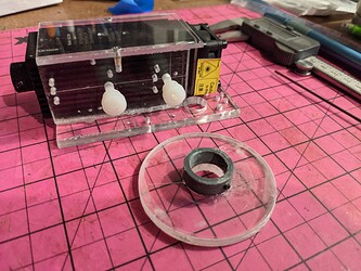
Assembled Carriage. Note the cutaway corner

Eccentric Spacer 

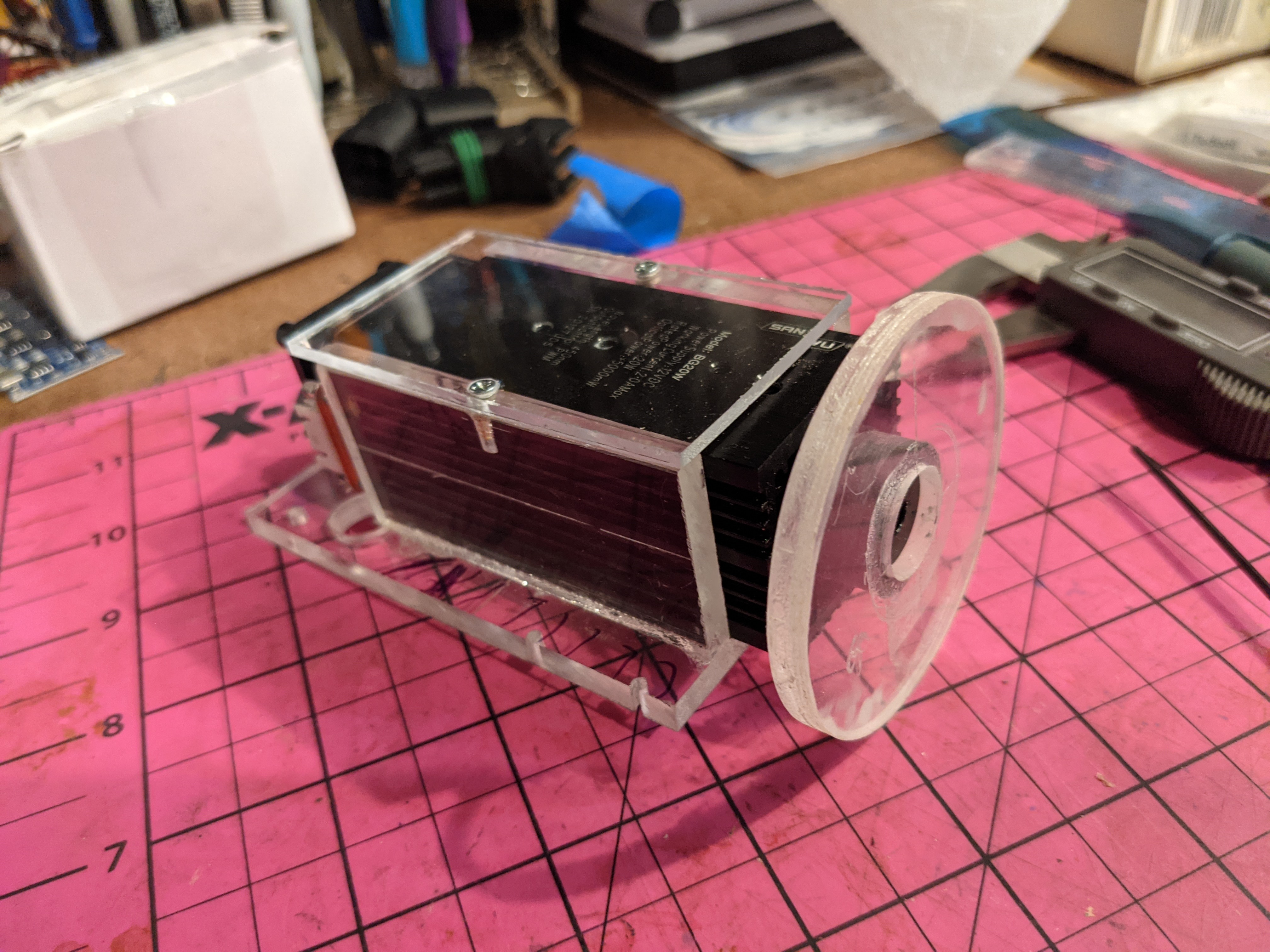
Fully Assembled Modified Carriage

Assembling the Tires and Axles

It's important to assemble the axles, spacers, and tires in the correct order which from bottom to top is:
  • Axle 
  • Lower plate
  • Eccentric Spacer
  • Tire
  • A small stock plastic spacer
  • Top Plate
  • Thumbscrew
Note: The Al spacer that comes with the eccentric kit and the large stock nylon spacer are not used.

Documents

This Document Contains 1:1 sketches of the bottom and top plate so that you can fabricate your own prototype bottom plate. So far it seems the top plate can be used as-is and a clone is unnecessary. You could also just drill the featured eccentric spacer holes on the stock bottom plate. That said I would wait until more testing is completed before hacking the stock plate.

Conclusion

The new carriage configuration has reduced the "play" and the carriage is substantially "stiffer". I have yet to test it in operation..... new problems may appear. 

This is not an expensive change ($2.20 for 2 spacers) and I am surprised that Vigotec didn't include this in their design. Then again perhaps there is something I missed... time will tell.

If you are having a problem with your FG-7X image quality and or holding FL, especially at higher speeds (vibration) you should consider this modification.

Enjoy and comment,
Don


Friday, July 16, 2021

VG-L7X

A K40 Traitor am I ?

After many years true my K40, I blame my MAAD* for falling prey to a sale on a 20W laser diode machine. I am now down the Vigotec VG-L7-X rabbit hole. 

*Maker Attention Deficit Disorder

My Vigotec Expectations & Plan

  • Build it…stock
  • Get the stock configuration working and characterize its abilities
  • Create documentation for the unit; controller schematic, stepper wiring, laser diode wiring & control
  • Convert/flash the unit's controller to Laser GRBL 
  • Drive it with Lightburn
  • Design and add safety and laser protection features
  • Design enclosure and lift mechanism so it can be used in a portable mode
  • Put in use, maybe engrave my yet-to-materialize electric dulcimer.

Specs


Getting Started


----------
Enjoy,

Comments are always welcome.

Please, consider using the donate button on the sidebar if you found this post valuable!

Don

Information in the VIGOtec ecosystem


About the VG-L7X


Purchased here:

VIGOtec VG-L7X (wifi)

Assembly

What's On the SD card

The unit comes with a USB SD card reader.
On the SD card which came with the machine and was plugged into the controller is a Gcode file:
  • sd_default.nc
Seems the VG-L7X runs on real gcode :). [yes but a proprietary version of GrBL]

sd_default.nc file

Videos

VigoTec Stuff on GitHub 

Custom Firmware upload

https://github.com/arkypita/Vigotech-VG-L7X/tree/main/CustomFirmware-VG-L7x

Flashing ESP

  • Copy of original firmware
  • Instructions on copying the resident firmware using esptool

Issues:

Maker Forums


This is only for the L7, not the VG-L7X

Finally figured my L7 out I think. Opened the “Read This” note in the software and it says to use the basic firmware when you want to use other software. I naturally installed the latest when I set mine up.SO. I went back and installed the ‘basic’ and low and behold LB is running. So here is the ‘note’ and good luck to you all!
**4.If you have other control software and want to use it, please upload the standard grbl firmware named ‘Standard_Grbl_1.1f.hex’. Or if you have the appropriate firmware just for the control software, upload it! If you want to use other engraving machine control software, please update the firmware of the engraving machine motherboard to general firmware. **

Upload Instructions for Standard Vigotec

  • Open www.vigotec.cn 7
  • Download file VG-L7 laser engraver
  • Open file and extract all
  • (Read the “ReadMe important” file, it has all explaind).
  • Open "driver_and_upload_tools file.
  • Open “Xloader” file
  • On “Hex file” open “Standard_Grbl_v1.1f.hex” file
  • On “device” select “Uno…”
  • Select the port you have
  • And “baud rate” must have “115200”
  • Upload!!!
  • Takes some time. When uploaded it must be ready to use any laser software (except the original vigotec).

Laser Diode Head

SanWu Model BG20W 

----------
Enjoy,

Comments are always welcome.
Please, consider using the donate button on the sidebar if you found this post valuable!

Don