INSTRUCTIONS:

Check out the new MoBeam posts! To find K40 conversion information use the "INDEX", "SEARCH" or "LABELS" sections in the sidebar.
Showing posts with label K40 Laser Power Supply. Show all posts

Monday, February 4, 2019

K40 Laser Power Control Characterization

Laser Power as a Function of Operator Controls

Recently +Ned Hill replaced his digital control panel with an analog one.
In the process he was thorough enough to take some measurements of the digital panels effect on laser power. Since Ned replaced the laser and the LPS this data may well describe an ideal K40 machine.
  • %PWM, 
  • Control Voltage (on the LPS-IN pin)
  • Laser Current 
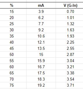
The +Ned Hill post and associated data are here and copied below for reference:

Tube%20power%20percent%20table 

This data shows the important relationship between the digital panels setting [%] and its relationship to the control voltage [V(G-IN)] on the LPS-IN pin and in turn the lasers power level. The LPS-IN signal results in the laser current seen at the ma meter [mA]. 

Observations About the Data

Multiple Linear Regression models can be constructed that more show us these relationships in mathematical form. Perhaps these simple math equations can help us predict the K40's performance and therefore more accurately choose settings.

I ran linear regressions on the above data to see if rational models could be derived to describe the laser powers behavior.

How Digital Panel Setting Control Laser Current Behavior

A regression was calculated using column 1 and 2 in the data above. The below equations represent a model of the relationship between panel settings and the resulting laser current.

equation 1: Tube Current = Digital Panel % * .2784 {R^2 = 0.996}**
equation 2: Digital Panel % = Tube Current/.2784

You can use these equations to estimate the laser current for a given digital panel setting or alternately estimate what panel settings will result in a what laser current.

The **R^2 value and this graph shows that the equations above should be pretty good predictors of laser current for a given panel setting. 

Note: the equation above predicts that at 100% Neds laser should draw approx 28ma of current.

How The Pot*** Setting Controls Laser Current Behavior

A regression was calculated using column 3 and 2 in the data above. The below equations represent a model of the relationship between panel settings and the resulting laser current.

equation 3: Tube Current = Control Voltage * 5.24 {R^2= .999]**
equation 4: Control Voltage = Tube Current/5.24

You can use these equations to estimate the laser current for a given pot setting or alternately estimate what pot settings will result in a what laser current.

The **R^2 value and this graph shows that the equations above should be pretty good predictors of laser current for a given panel setting. 

Note: The equation above predicts that Neds laser should draw 26.2 ma with the IN voltage at 5vdc.

*** the pot is sometimes called "Current Regulation" on stock machines that come with a pot.

How Do I Know What the Pot Setting Is?

Good question! The equation above uses "Control Voltage" as one of the variables so how do you know that value? Install a DVM on the POT. It tells you the control voltage it presents at the LPS-IN pin.

To use this schema read or set the pot until the DVM reads the voltage [control voltage] you calculated using equation 4 above. 

Your Mileage May Vary?

Statistical models are based on empirical data like that given in this post can be in error in a few ways, garbage-in-garbage out. 
+Ned Hills data is likely "IDEAL" since it was taken with a new tube and LPS. As such it should be a great reference as to what a K40 machine can do.

Here are some sources of error (assuming I did the math right):
  • Your LPS is weaker than Neds new one
  • Your Digital panel is defective 
  • The 5v supply used to drive the LPS-IN pin is an incorrect value
  • Your tube is weaker than Neds new one
  • Your mileage may vary

Local vs Programmatic Control

When firing the laser from the control panel the power is entirely controlled by the Digital Panel or Pot Settings. Therefore the equations above apply. 

However when under programmatic control from a PWM signal on the LPS-L pin the lasers power control is more complex. Its power is the product of the controller PWM % and the control voltage on the LPS-IN pin.

Using the Digital Panel To Set Laser Power

Laser current = (PgmPwr/100) * (DigitalPanel * .2784)

whereas: 
  • PgmPwr = the power setting in the control software as a percent
  • DigitalPanel = the setting on a K40 digital panel as a percent

Simple Example:

- DigitalPanel is set to 100%
- Lightburn power setting is 50%

     Laser current = (50/100) * (100*.2784)
     Laser Current = .5 * 27.8
     Laser Current = 13.9 ma

With the above settings when you push the test button you should see the meter read 27.8 ma
When running from program control you will run much less than 27.8 since the static value set by the digital panel will be reduced by any program setting less than 100%. 

Using The POT To Set Laser Power

Laser current = (PgmPwr/100) * (ControlVoltage* 5.24)

whereas: 
  • PgmPwr = the power setting in the control software as a percent
  • ControlVoltage = the voltage on the LPS-IN pin as set by the pot

Simple Example:

- Pot is fully on i.e. LPS-IN = 5vdc
- Lightburn power setting is 50%

     Laser current = (50/100) * (5*5.24)
     Laser Current = .5 * 26.2
     Laser Current = 13.1 ma

Is This Academic Knowledge?

If you expect your system to act exactly like +Ned Hill's then yes this may just be interesting information about Ned's machine. If however you value this information as a model of an ideal K40 machines laser power control behavior more value can be extracted. 

Ideas I have for using this knowledge are:

After taking a few settings *** on a machine you may;
  • See how close it performs to ideal
  • Create a model to match your actual machine by factoring the ideal model
  • Use the model to aid in choosing operational power settings
  • Attain a gauge to track your machines performance as it wears out
  • Troubleshoot laser control problems without electrocuting yourself  
*** take 3 measurements of laser current vs control voltage or digital panel settings.

Donate?

If this post helped you solve a problem, saved you time or was otherwise useful consider donating. Use the link in the upper right of the site.
Donations fund some of the expense of tools and materials for my shop and lab so I can bring you more content like this. 

Also let me know if there is other content you would like to see me explore!
_____

Thanks and please comment
Don

Replacing the K40's Digital Panel with an Analog one

Why replace the panel?

It is not uncommon for the K40's digital panel to fail and more and more users are realizing the value of having a pot for control and an analog meter read laser current.

The digital panel

Understanding the k40 digital control panel

Adding an analog meter.

Adding-analog-milliamp-meter-to-k40.html

Converting the Digital Panel to Analog

Recently +Ned Hill had a LPS failure and tube replacement and decided to replace the digital panel and do a C3D upgrade.
We thought posting the conversion would be useful to others in the community

Schematic

I added a conversion diagram to the existing schematics I had for the digital panel.
It is located on the tab "Convrt 2 Analog".
https://www.digikey.com/schemeit/project/k40-powerled-v30-PM4QJBO303GG/


Conversion Instructions:

These conversion instructions are for supplies with all GREEN connectors. I can add the equivalent for other supplies upon request.

This conversion entails replacing the digital panel with an analog equivalent. The new analog panel has a switch, momentary push-button, pot, and digital voltmeter. The harness that goes from the LPS to the digital panel can be reused with the addition of two wires. These instructions refer back to the schematic.

-Build and mount the new analog panel (blue area)
-Remove the connector from the digital panel (orange area)
-Cut off the connector and strip back the wires
-Reconnect the 4x digital panel wires as shown in the schematic to the new panel (blue area)
-You will have to add 2x wires to the harness the G and the 5V

Note: this schematic also shows an installed pot and an associated control voltage DVM

Extracted from the schematic

Pictures From +Ned Hill Conversion

Supply Connections


Purchase Links

Please buy your parts using my affiliate links. It costs you nothing and it helps fund my activities. I defined a kit for this project which contains all the parts and links to amazon.
The entire kit is here and points you to these parts on Amazon.


Contributors

Thanks to +Ned Hill for his contribution to this post.

Donate?

If this post helped you solve a problem, saved you time or was otherwise useful consider donating using the link in the upper right of the site.
Donations fund some of the expense of tools and materials for my shop and lab so I can bring you more content.

----

Thanks, and please comment,
Don

Saturday, May 26, 2018

K40 Laser Power System Troubleshooting Guide

So Your Laser Won't Fire?

The laser power and control system in a K40 is a relatively complex and its the most unreliable subsystem of the overall K40. Therefore a lot of time is spent diagnosing and subsequently replacing and repairing parts of this subsystem.
It seems important that we capture what we have learned about troubleshooting and fixing K40's. 

Donate:

Please consider donating (button to the right of this post).
Your donations help fund additional research (like this one), tools and parts that I will return to the community as information.
For other information on the K40-S build use the  K40-S BUILD INDEX with schematics

Is it your laser power or the laser tube that is bad?

Good question! We don't have a definitive way of pointing to a bad tube but we can insure that the control system that drives it is working properly. Well almost. We can verify operation all the way to the input of the LPS but beyond that the HV characteristics of the laser tubes drive makes clear component identification dangerous, uncertain and expensive.
This guide helps eliminate everything up to and including the input of the LPS as the culprit. If everything is good to the LPS then I would:
  1. Replace the LPS 
    1. If you have certain symptoms you can try replacing the LPS's HVT. This is the most common type of LPS failure
      1. Repairing-k40-lps
  2. Replace the laser tube

The K40 Laser Power System Troubleshooting Guide

This guide provides K40 owners a flow chart for troubleshooting the Laser Power Control and Supply subsystem.

The Guide To Troubleshooting

The Elements of a K40 Laser Power Control Subsystem

  • Input power
    • AC plug and fuse
  • Control panel
    • Current control pot or digital controls
    • Laser enable sw
    • Laser fire Test button
    • AC power button
  • LPS
    • The high voltage supply
    • The laser enable loop
    • The local test PB
    • PWM input (L)
    • Local power control (IN)
  • PWM generator
    • The controller that converts gcode S commands to a PWM signal.
  • Laser
    • The laser tube that generates the optical power

Hints of Tube & LPS Failures

If after you check your laser power system with the troubleshooting guide and all is OK here are some additional hints:

Your tube might be bad if:

  • It does not light up at all
  • There is an arc from the anode to the frame. When the tube is bad it provides no load to the LPS. An unloaded (bad tube) LPS will often arch violently to the surrounding case
  • It has cracks
  • There is no current on the meter when the test switch is activated.

Your LPS might be bad if:

  • There is arching inside the supply
  • The mili-ammeter reads erratically at currents above 4ma
  • The current is lower at higher power settings than at lower power settings

Errors

If you find any kind of error or lack of clarity please make a suggested change in the comments.

Enjoy and comment,
Don

Saturday, February 24, 2018

Will a 40 Watt LPS Drive a 60W Laser?

Under-powering a Laser Tube

Caution: these are preliminary musings .....

Recently +Chuck Comito presented me with a question regarding how his 60W laser would perform with his stock 40W Laser Power Supply (LPS).
I hadn't spent much time looking at LPS specs matched against Laser Tube specs. I just assumed that if you got a bigger tube you had to get a bigger supply. 
Although to get to full power you will need a LPS that will output enough current to match the tubes specification, you can under power your laser ... theoretically. 

That said, +Chuck Comito is running a 60W K40 with a 40W LPS somewhat successfully, still testing. 

Donate:

Please consider donating (button to the right of this post).
Your donations help fund additional research, tools and parts that I will return to the community as information.
For other information on the K40-S build use the  K40-S BUILD INDEX with schematics

Why do we care?

Like most users when my tube goes bad I plan to upgrade to a higher power tube. We all know that our K40 really is a K30-35 in that these tubes don't actually output 40 watts.
30 watts is marginal for cutting thick materials and experience has shown us 50-60 watts is a better range for us makers.
The cost of upgrade would logically include the cost of a new tube and a higher wattage supply. This post suggests that you can upgrade your tube using your current K40 40 watt supply. That't a $100-150 cost savings and it allows us to use the stock supply to end of life.

The short theoretical analysis

1.) You can run your 60 watt laser with your 40 watt supply if you keep the current <=16MA
2.) Although at 16ma you will not reach 60 watts you will achieve a marked increase over what you had before at the same current.
3.) You can reach 60 watts if you run the supply at full capacity (22ma) but this will likely reduce its life.

My learning: you can upgrade your machine to 60 watts without getting a new supply unless you need run at the full 60 watts.

The long theoretical analysis...............

We know what the voltage vs current curve looks like, see the ref. at the bottom of this post.
I do not know what laser output vs current curve looks like when the tube is in the Normal Glow region [update: I added an attempt to model current vs optical power in the model below].
I assume that as long as the tube ionizes and the voltage is held at the operating voltage it will output light proportional to its current.

...We know that the needed trigger voltage relates to the length of the tube
...We know that the supply will current limit based on its pot setting up to close to 100% DF where is will be at max current.

Can you use a 40W supply to power a 60W laser?

This question of LPS wattage vs laser tube wattage is one I never did any research on. a I never compared the specs of supplies and laser tubes. So in the model below I captured some specs for comparison. I used similar supplies and tubes just different wattage's.
If you look at the specs for tubes and supplies in the model you will notice that the HV specs for a 60W tube can be met with a 40W supply! This means the supply will provide enough trigger to ionize and hold that ionization level.
There is a small mismatch between the current specs when using a 40w supply with a 60w tube. Note that the 40W supply must run at MAX current to provide enough current for the 60W tube, whereas the 60W supply provides enough current running below its max output i.e. its operating curent.

Assuming your tube and LPS have specs like those below, I would theorize that you can operate your 60W tube with a 40W LPS operating in the range <=16 ma and not >22.

The 40W LPS current will not likely get you to a full 60W. If things were linear, which they never are, you could estimate that with a safe LPS current of 16ma you will run 16/20 = 73% of rated power or 43.6W.

This may seem like a hugh loss of power but consider that your 40W was probably putting out 30W (as some high current). You now have a 13.6 watt (45%) increase over your previous setup. This means you have more power at a lower current. Not bad since you saved $100-200 in your 60W upgrade.

A Model

Using a purely specification based comparison of LPS's and laser tubes we can build a model to better understand how matching/mismatching LPS and laser tubes might perform.  Here is the analysis that led me to the conclusions I summarized above:


Enjoy;
Comments and corrections expected
Don

Tuesday, February 20, 2018

K40 LPS Silk Screen Error

K+/K- Reversed On Newer Machines

Reversed Silk Screen [K40 with digital panel]
Correct silkscreen [non digital panel]

Donate:

Please consider donating (button to the right of this post).
Your donations help fund additional research, tools and parts that I will return to the community as information.
For other information on the K40-S build use the  K40-S BUILD INDEX with schematics


K+ & K- Silkscreen

On some new machines it seems that K+ and K- are reversed. This does not create a problem except when you are rewiring or testing. The silkscreen is printed wrong not the signal.

LPS Connection Function & Test

Here is a table that shows the voltage at these terminals when functions are asserted. 


Donate:

Please consider donating (button to the right of this post).
Your donations help fund additional research, tools and parts that I will return to the community as information.
For other information on the K40-S build use the  K40-S BUILD INDEX with schematics

Enjoy,
Comments and corrections expected...

Don

Thursday, July 27, 2017

Repairing the K40 LPS #1

Background

It is quite common for the Laser Power Supply (LPS) in your K40 to fail. Although our knowledge of the LPS design has been dramatically increased it is still unclear why certain parts of the supply fail.

I continue to collect failed LPS's dissecting each to see if we can find a reason for failure and solutions to potentially extend their life.

The bad news is that the LPS failure rate seem to be quite high. The good news is that they don't cost that much. You can get a new supply from China vendors for 60-$70. It almost seems that the LPS just like the laser tube should be considered a "consumable".

K40 LPS are high energy supplies and it is very easy to experience cascading failures when making repairs. If you consider the cost the components you could easily spend as much on a repair as a new supply!

This post is still a WIP!

Version

The stock K40 comes with LPS's in a few flavors. We have tried to categorize these supplies using the color of their connectors as a gauge. K40 LPS's typically have either all green connectors or both green and white connectors.

https://donsthings.blogspot.com/2017/01/k40-lps-configuration-and-wiring.html

Resources

We have a fairly accurate schematic and have identified most of the replaceable parts.
Other posts regarding LPS information can be found under this search link:

Donate:

Please consider donating (button to the right of this post).
Your donations help fund additional research, tools and parts that I will return to the community as information.

For other information on the K40-S build use the  K40-S BUILD INDEX with schematics

I also collect failed LPS in an effort to better understand them and their modes of failure. If you want to donate comment below or PM me at +don kleinschnitz 

Typical LPS failures

My research on LPS failures has revealed three common component failures: 


  • The laser will not fire or fires at lower and often erratic current levels including arching inside the LPS
    • Replace the HVT, 
  • The fuse on the LPS pcb blows
    • Replace the AC Bridge Rectifier, 
  • The 24V or 5V power is missing along with other symptoms
    • Replace DC power supply PWM controller

I will discuss these three components and their replacement in some detail but first lets discuss safety and life threatening risks.

I do not recommend repairing your own LPS!


That said, removing and replacing components in a powered down LPS can be done successfully and safely if done correctly.


I am not guaranteeing that if you follow these procedures you will be safe.


ANY REPAIR THAT YOU DO IS AT YOUR OWN RISK AND IF YOU PROCEED PAST THIS POINT YOU ACCEPT THAT RISK AND ITS CONSEQUENCES. 
The author does not make any warranties about the completeness, reliability and accuracy of this information. Any action you take upon the information on this site is strictly at your own risk, and the author will not be held liable for any losses and damages in connection with the use of this information.


Need some proof that an operating LPS is lethal.

CHECK THESE OUT

DO NOT EVER! 

  • Power up your LPS outside of a K40.
  • Power up the K40 with the anode or -L wires disconnected
  • Access the laser compartment with the AC power plugged in.
  • Access the laser compartment without first grounding the anode with a "chicken stick"* and its procedure" with interlocks in place.

Going About a LPS Repair

I haven't found a magic way to tell what part is bad. One or more of the parts cited below can cause one or more problems by themselves or as a catastrophic failure.

Here are some scenarios I have seen:
  • Scenario 1: F1 blown => Do repair #1= replace F1, BRI
  • Scenario 2: Fuse still blown after Repair #1 => Do repair #2 = replace F1, BR1 and PWM
  • Scenario 3: Arching, low or no power without scenario 1: Do repair #3 = replace HVT
I will add more scenarios as research continues.

I will refer to this picture for these repairs

Prepare the K40 for any type of LPS repair

STOP: THIS PROCEDURE MUST BE FOLLOWED FOR ANY LPS REPAIR OR YOU WILL GET SHOCKED!

  1. Remove the main AC power plug
  2. DANGER: In the laser tube compartment ground the anode of the laser using Procedure A below.
  3. Unplug all the connections to the LPS.
  4. In the laser compartment, pull (or cut if you have to) the sleeve from the anode. Remove any silicon insulation and remove the anode wire from its post. If the wire is soldered, un-solder it but be careful not to overheat the terminal in the tube as it may damage the tube.
  5. In the right K40 compartment loosen or remove the LPS hold down screws. Sometimes the front screws can be removed and the rear screws loosened making replacement easier. From inside the right compartment pull the anode wire back through the laser compartment wall and into the right compartment. Be careful not to chafe or abrade the anode wire as you pull it through orifices in the cabinet. 
  6. Remove the LPS from the K40 and place it on a work surface. "NEVER POWER UP THE LPS OUTSIDE OF THE K40!.

High Voltage Transformer (HVT): Replacement Procedure

  1. Test for bad HVT: position the head over a piece of mark-able material and then press the "TEST" button on the LPS.
  2. Verify Symptoms: the laser does not fire or fires at reduced power. In addition you may hear crackling noises coming from the LPS or the laser compartment
  3. By now you should have completed  "Prepare the K40 for any type of LPS repair": as described above if not STOP & DO IT NOW!
  4. Remove the LPS cover screws and lift off the cover. The fan will be attached...
  5. Unplug the FAN
  6. Locate and Remove the HVT: 
  7. Some HVTs are screwed to the frame and have a 3 pin connector. On this type remove the HVT from the frame and unplug the connector. Go to step 9.
  8. Some HVT's are bolted to the PCB. In this case you have to remove the PCB to get to the nuts.
    1. Use Procedure B to remove the PCB
    2. Remove the HVT
      1. Turn the PCB over and remove the nuts holding the HVT.
      2. Replace the HVT and its nuts.
      3. Reinstall the PCB into the chassis by reversing Proceedure B
      4. Go to step 8.
  9. Replace the HVT
  10. Replace the HVT in reverse of the order you removed it.
  11. Plug in the FAN cable
  12. Replace the LPS cover
  13. Reinstall the LPS into the K40
  14. Use Procedure C to reconnect the LPS to the laser tube
  15. Use Procedure D to test the LPS


Bottom side of PCB showing alternate HVT mounting

Bridge Rectifier: Replacement Procedure

BRI: note its orientation. + of the bridge is on the right in this view
  1. By now you should have completed  "Prepare the K40 for any type of LPS repair": as described above if not STOP & DO IT NOW!
  2. Remove the PCB using Procedure B: Removing and Replacing the PCB
  3. Locate the Bridge Rectifier BR1 on the front of the PCB
  4. On the back side and using "solder wick" and a hot iron suck all the solder from the joints of BR1. Alternately you can cut BR1 out from the top side of the PCM and then pull the remaining legs out while heating. Finally suck the solder out of the joints leaving open holes for the new part.
  5. Replace BRI by inserting a new part and re-soldering its three legs. You can replace BRI with a direct replacement or substitues.
  6. IMPORTANT: Insure that the new BRI is oriented with its "+" lead to the right as this picture shows. The "+" marking is not shown on BRI in this view because its on the other side . You can see the "+" silk screened on the PCB. Just in sure that the replacements part "+" is aligned with the "+" on the PCB.
  7. Locate F1 and remove using the same soldering method as #4. 
  8. Replace F1
  9. Replace the PCB using Procedure B: Removing and Replacing the PCB
  10. Plug in the FAN cable
  11. Replace the LPS cover
  12. Reinstall the LPS into the K40
  13. Use Procedure C to reconnect the LPS to the laser tube
  14. Use Procedure D to test the LPS

COMMON  PROCEDURES

Procedure A: Discharge the machine

Make a discharge stick ["chicken stick"] (see photos's below):
See picture below, I think it is self explanatory. Mine is about 2ft long. You can use a dowel or PVC like mine. BTW I can sell you one for $200 ...:).
Note: I recommend PVC as wood can have high moisture content.

Ground the end of the wire opposite the taped end of the wire to bare metal on the cabinet. The terminal post on the back of your K40 is a good place after you insure that it is really grounded to the cabinet. You could replace the alligator clip on my example with a banana jack to make it more convenient.

Hold the end of the stick at the end opposite the taped wire. Put your other hand behind your back do not touch anything else with any part of your body.

DO NOT TOUCH THE DISCHARGE STICKS WIRE

Probe the bare wire end in and around the anode to discharge it before you enter the compartment.

If you see a spark just silently say "thank you Don, that woulda hurt!".


Procedure B: Removing/Replacing the LPS PCB

    1. Remove the 3x A screws from each corner of the PCB.
    2. Remove the 2x B screws that hold the power FETs to the chassis
    3. Remove the screws holding the 5V Reg and low voltage PWM controller to the chassis and associated heat syncs.
    4. Retain all screws and thermal insulator pads
    5. To replace reverse steps 1-4, insuring that you include the heat sync thermal pads under PWM and 5V reg

Procedure C: Connecting the LPS to the Laser

  1. Replace the anode wire in the same way it was connected, twist, solder or screw.
    1. If soldering use minimal heat. Some recommend using Teflon tape to hold wires that are twisted see video below.
  2. Route and restrain the wire in the same way. Usually tie wraps around the tube moving away from the anode end toward the cathode end.
  3. Flow silicon around the anode wire connection (use the white tube that came with your K40) 
  4. Push the silicon tube over the wet silicon filling the tube. If you had to cut off the tube you will need to replace it with a peice of silicon tubing.
  5. Add more silicon to the top of the silicon tube if needed
  6. Let dry for 24hrs before using the machine
Silicon pot-ing materials: 
  • Permatex Blue RTV Gasket Maker. Available in auto and big box hardware stores.
You can use a plug-able HV connector to connect the laser HV lead to the LPS. I recommend this approach because once done you can avoid disconnecting the anode connection when troubleshooting or replacing the supply or laser. Also consider buying a laser tube with the anode pre-connected.

HV plug


The videos below show connection and disconnection of the tube from its supply and can be used as reference example:

LPS and/or Laser Tube Replacement Kit

Procedure D: Testing the repaired LPS

Unfortunately there isn't a safe way to test a LPS outside of the K40, you will have to reinstall it in the K40 and test its operation by checking while actually marking. If you repaired this supply as a spare verification will have to wait :(.

"NEVER POWER UP THE LPS OUTSIDE OF THE K40!.

Enjoy and comment


Maker Don

Thursday, June 29, 2017

K40 High Voltage Transformer Autopsy #2

Background

This is a continuation of http://donsthings.blogspot.com/2017/06/k40-flyback-autopsy.html. In the previous post both myself and +Nate Caine tore down High Voltage Transformers (HVT) as part of our quest for knowledge of the details of the K40 LPS internals.
In this tear down the potting material was removed chemically in hopes that the circuit and its components could be kept in tack. The transformer was also sectioned a means of understanding its design.

Donate:

Please consider donating (button to the right of this post).
Your donations help fund additional research, tools and parts that I will return to the community as information.
For other information on the K40-S build use the  K40-S BUILD INDEX with schematics.

The schematics for the LPS:


Removing the Potting

The potting was mostly removed using paint stripper. Caution: use gloves as this stuff is caustic.
Use gloves and eye protection this stuff is caustic
HVT submerged in glass container
The potting removal took nearly 2 weeks of repeatedly checking and refreshing the solution. The potting will come off in flakes which I washed off with each refresh. Unfortunately the stripper de-laminated the capacitors and destroyed their covering so no labels were visible. The diodes had no labels. 
It is probably worth experimenting with other chemicals that might work faster and not destroy the components coating but this worked good enough to get the information we needed.

Discovering the Circuit

The component connections were carefully observed as the potting removal proceeded. This version (and it seems there are more than one) used 2 HV diodes and 2 HV capacitors in a Voltage Doubler configuration. In this case (unlike the previous autopsy) there were no parallel diodes.

Circuit removed from the potting. Overlay showing connection of secondary.

Image result for voltage doubler
Example circuit. These exact components are not what is used in a K40 LPS

HVT Cross Section and Analysis

After the potting removal step the transformer was sectioned with an abrasive metal blade on a Dremel and then polished on a marble flat plate with 600 grit wet paper until the wire cross sections was visible.

Left: five section secondary. Right one section primary winding's


Primary Winding

The primary winding consists of 40 turns of 21 wire bundles.
Primary winding


Secondary Winding

The secondary winding consists of 5 sections of  +400 turns wired in series.

Primary winding connection leads


One section of secondary winding
The secondary does not have a center tap and is directly connected to the junction of the diodes and the minus leg of the lower capacitor. See voltage double'r example.

HVT Design

The HVT consists of a primary winding and a 5 section set of secondary winding's.

HVT Primary

The HVT primary has 40 turns in which each turn is a twisted set of 21 wires. The primary effective wire size indicates that the primary is designed to handle much more current than the secondary.

HVT Secondary

The secondary has 5 winding sections insulated from each other but connected in series. 

The turns wound on three different secondary sections were counted, one on the first  HVT and 2 from the second HVT. The first count = 499 and the two sections counted on the second HVT = 452 and 471 respectively. 
I don't think the difference in the counts are caused by counting errors. Its seems that the turns on each section are not the same (Rt). I did not further investigate this variance in turn counts as I do not think it will materially change the outcome of the analysis.

Turns Ratio

Using an average of the last HVT 2 sections turns count lets assume:  

  • Average turns per secondary section = 461.2
  • Number of secondary segments = 5
Total # of turns = 461.2 * 5 = 2306 total turns on the secondary

Therefore the HVT is a 40t to 2306t HVT transformer, a ratio of 1:57.65

Estimating Output Voltage

The voltage at the output can be expressed as:
Hv = Pv * Rt * Mv
where:
  • Hv is the output voltage
  • Pv is the voltage on the primary
  • Rt is the ratio of primary to secondary
  • Mv is the voltage multiplication factor
Therefore for every 100V on the primary the output = :
Hv = Pv * Rt * Mv
11,300 = 100 * 57.65 * 2

Calculating HVT Primary Voltage

The typical K40 PS output voltage is specified at 23,000V @20ma.


If we solve the above equation for Pv:
Pv = Hv/(Rt*Mv)

And use it to estimate the primary voltage at spec: 
Pv = 23000/(57.65*2)
Pv = 200 Volts

By inspection of the LPS schematic I estimate the HV buss to run at about 240-300 volts, 40 volts larger than the estimate above..

This error of 40 volts on the primary equates to about 2,306 volts on the output or 10% of the specified output. This error can easily be the result of an error in estimating the total turns across the 5 secondary sections [perhaps each secondary section has different turns] or simply differences in any given manufactures specified HV output.

Primary Current Estimates:

The specified max current output for a typical K40 supply is 20ma. In a transformer the voltage on the output is increased by the turns ratio. So to the current in the primary is larger than the current in the secondary by that same ratio (Rt). 

Therefore: 
Pi = Si * Rt
where;
Pi = the primary current
Si = the secondary current
Rt = the turns ratio

Solving for the primary current using K40 LPS specs and given the output current = .02 amps
Pi = .02 * 57.65 = 1.1 amps

Learning's

A K40 HVT contains a high current primary and a multi-section secondary. A high turns ratio secondary in combination with a voltage double'r  creates approximately 11,300 volts per 100 volts of primary voltage.
This autopsy provides a model of the HVT that more completely characterizes a key component of a K40 LPS... its HVT.

If the above analysis holds true then the following has been verified:

  • K40 LPS are easily capable of voltages in excess of 23,000 volts
  • A K40 HVT's include a voltage doubl-er in its output stage
  • A K40 HVT cannot be tested using a standard DVM because it cannot forward bias the internal HV diodes. Each HV diode is actually a serially connected stack of 20 or more diodes. Voltages that exceed 120 volts might be necessary to forward bias both the diodes in this double'r configuration.
  • K40 HVT's are not repairable

Suspicions of K40 LPS Failure Modes

I suspect that LPS failures fall into these categories:
  • AC plug swapped with the DC plug damaging the supply's enabling circuits
  • The low voltage PWM controllers output shorting, blowing itself and the bridge rectifier.
  • The Bridge rectifier failing under load. 
  • Arc's causing excessive secondary current, opening the HVT's diodes.

What's Next To Do On the K40 LPS Quest

  1. Map the actual voltages in the LPS including the primary's HV buss to further verify the above model.
  2. Scope and capture dynamic views of the internal circuitry's operation.
  3. Scope and capture dynamic views of the Lasers current and voltage while marking.
  4. Review the component specifications and verify that specifications are not being exceeded in actual operation.
  5. Noodle a safe HVT DIY HVT tester. 
  6. Noodle a safe and DIY HV tester

Enjoy and comment
Don