Adjustment Slide
Not yet knowing what's the best way to adjust focus for my L7X I decided to build a slide that would enable simple adjustment of the diode modules vertical position.
Available Designs:
I also found a few on:
This is a simple design and concept. Replace the stock carriage interface plate with one that has a sliding channel for the diode module. The up/down motion is achieved by loosening a binding screw, sliding the laser module, and then retightening the screw.
This may be too simple for long-term use but I needed to make a fast prototype that would allow a large yet simple range of adjustment. Using this proto I will identify how much range & precision the vertical adjustment needs to have.
Once the adjustment needs are identified I may change the approach to a screw slide.
Stock Interface Plate
This plate is removed from the unit, the slide replaces its function. I used the stock interface plate as a template to get the holes of the new plate in the right place.
Tape this plate to the blank you are using for the new slide and drill through it to get the fastening holes in the right place.
Slide Design
The slide consists of 3 parts. backplate, side guide, front cover. This is a simple design to help me understand what the final design will need in regard to adjustability. If the head does not need much vertical adjustment and accuracy is not a factor, this may be a good approach. Otherwise, a screw-driven approach may be better.
Backplate:
This plate mounts directly to the carriage using the stock top thumbscrews. For this plate to mount flush on the carriage it must have features drilled to accommodate the belt and tire mounting bolts.
Note: you will notice many holes in the photos of the slide. I reused some old plastic that was previously drilled. Therefore ignore the holes in the picture and reference the drawings.
 |
| Note the heads of the tire mounting bolts and belt retainer |
Side Guides:
These two parts create the walls that the laser head slides within. There are two 8-32 nylon adjustment thumbscrews that hold the head in position in the slide.
These parts also have two #4-40 inserts pressed (with heat) into their edge. These inserts are used to mount the front cover. I used SAE fastners but
any type small fastener that will fit edgewise into the guide will work. I got my inserts from
McMaster.
The thumbscrews came from my fastener collection but most any 8-32 fastener can work. I think I got them at Lowes, Ace is another place to check. I used nylon to prevent galling the side of the laser module.
 |
| Right side view |
 |
| Left side view |
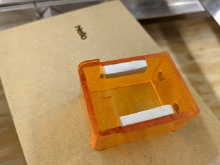
Front Cover:
The front cover is made from .
080 acrylic but thickness is not critical. This cover exists mainly to keep the
side guides from deflecting when the adjustment screws are tightened against the laser module. In a future design, this cover may be replaced as part of a safety cover once I verify what the focal point dimensions are.
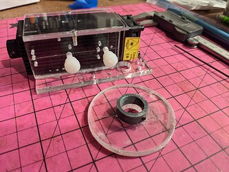
Update: modifications
I had to cut the assy off just below the screws. At the proper focal distance, the slide was in the way of the microscope and blocked me from adjusting the lens. The focal point was set at 30mm below the lens's surface.
*USB microscope used to set the focus.
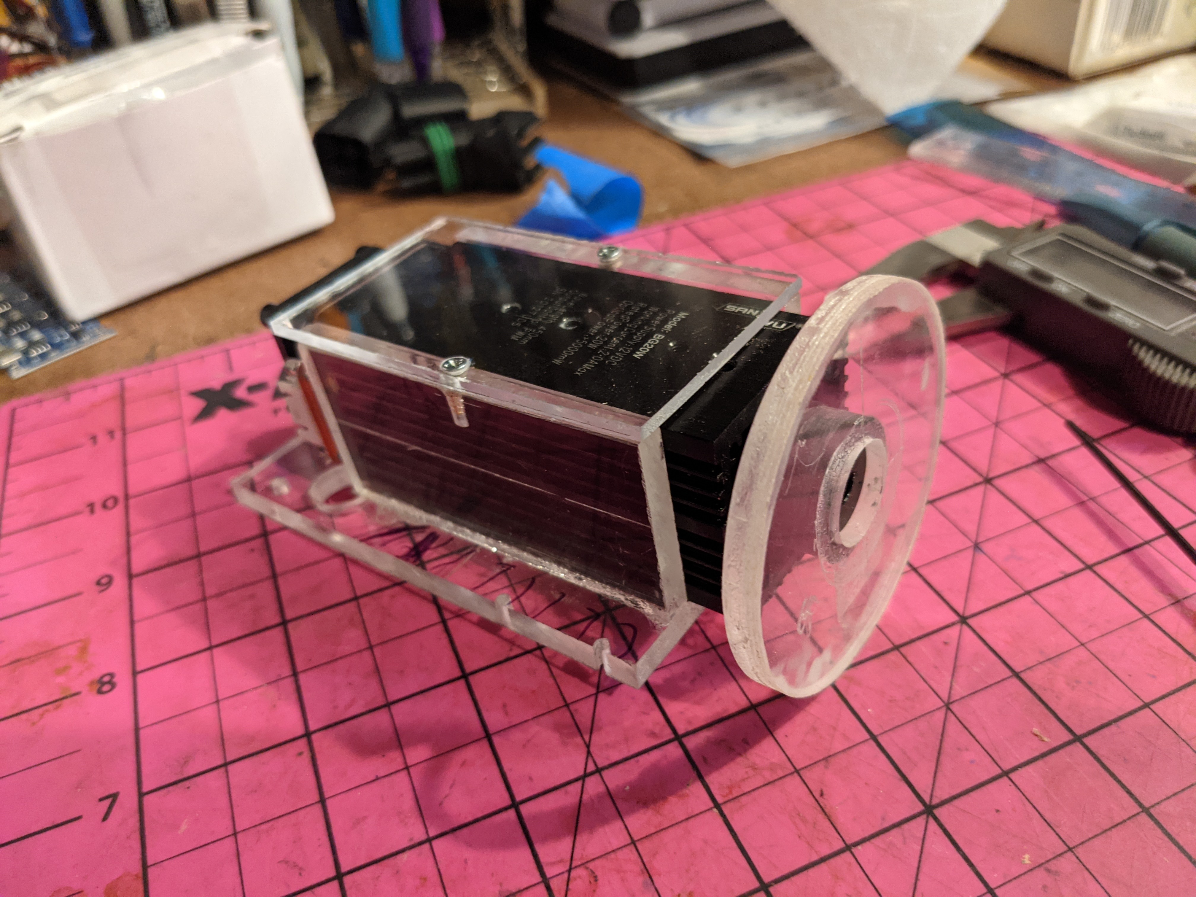
Modified Slide
Picture
Slide Fab
Attached are 1:1 traced drawings (not CAD) in case you want to fab a slide. These drawings are traced from the actual part and some nominal dimensions taken from the actual parts are added.
I made this from 1/4" & .08" clear plastic (Lowes), cut it on the table saw and drilled with metric twist drills. The larger holes were drilled with Forstner and step bits.
I clamped the stock adapter plate to the new slides backplate as a template to get the mounting features in exactly the stock positions. I drilled through the stock plate and into the new backplate.
The laser head was mounted in holes B (see drawing). Make sure the head is at 90 degrees to the back plate. Then
acrylic glue was applied to the side of the guides which were then clamped to the laser. This insured an accurate fit to the laser module.
Drawings
A simpler Slide?
Trace Method of Prototyping
When I am modifying an existing machine I like to build proto's by what I call the
trace method. I remove the original parts that I want to modify or replace and use them as a template for drilling & cutting the features that I want to keep. I also sketch a 1:1 drawing for reference and sharing. I attach the template using
double-back tape or simply copying the 1:1 drawing and gluing it to the surface with
stick glue.
If I plan to make a more precise or easily replicated part I create a CAD/CAM version, otherwise, I am done. If you need a CAD/CAM version let me know in the comments.
----------
Enjoy,
Comments are always welcome.
Please, consider using the donate button on the sidebar if you found this post valuable!
Don


