INSTRUCTIONS:

Check out the new MoBeam posts! To find K40 conversion information use the "INDEX", "SEARCH" or "LABELS" sections in the sidebar.
Showing posts with label K40 PWM Control. Show all posts

Monday, March 6, 2017

Laser Response Charcteristics

Laser Response Characteristics

I moved the research that I have been doing into "laser response" to this post to capture it in a more focused way. 
Understanding the lasers response is an important part of getting to the best engraving control possible. The engraving control basics are described in Engraving-and-pwm-control.html. 
Understanding the relationship between the HV power (voltage and current), the tubes gas discharge characteristics and the lasing process of the C02 is integral to an understanding of how to optimize digital control of its power.

Donate:

Please consider donating (button to the right of this post).
Your donations help fund additional research, tools and parts that I will return to the community as information. For other information on the K40-S build use the  K40-S BUILD INDEX with schematics as a source of information 

Links to Related Posts

Electrical Modulation of a CO2 Laser

"Low frequency modulation can be achieved by pulsing or chopping the electrical power to the discharge. As the frequency is increased, the effect of the varying input decreases and above a few kHz, disappears entirely. The output of a DC or RF excited CO2 laser are both CW beams.
(From: David Toebaert (olx08152@online.be).)
This remark really holds for any kind of CO2 laser (the effect gets worse at higher pressure). It's just nature: it takes time for the molecules to 'meet' one another causing the delay. For a laser at 100 mbar (around 76 Torr) and a typical gas mix, the cut-off frequency is about 3 kHz. Above that the modulation of the input power is strongly damped and hardly visible anymore in the output power.

Simply think of the discharge as a *low pass filter for the input power, no matter how you excite the discharge. Of course, it's possible to modulate the input power at much higher frequencies (e.g. an RF supply can easily be modulated up to 100 kHz, that is, the Mhz signal is modulated at 100 kHz), but from the point of view of wanting to modulate output power, it makes no sense. Maybe it's beneficial for other reasons (e.g., discharge stability)."


*Whats a low pass filter?

The Effect of Modulation Cutoff Frequency 

The article above says that the laser cannot transfer input power changes that occur at a rate > than 3kHz. That means that the max time between changes that will be useful is: 3kHz  = 1/3000 = .00033 = 330 us. 
This means that in the model above the suggested pwm period (200us = 5kHz) is longer than the response time of the lasers gas ionization. 

If that is true then:
  1. The PWM period needs to be much longer or the gantry slowed down considerably
  2. The much faster times I measured (2us) by monitoring current suggests that it is not a  indication of the speed of light output. Is the current flow during ionization much faster than the light output?
More testing needed :(.


Laser Gas Discharge Characteristics

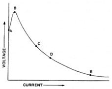
Negative Resistance
Negative resistance of a gas discharge: the voltage and current increase as described by ohms law until the discharge point. Then rapidly the voltage decreases and the current increases.

The hypothesis used in testing (above) and modelling; that the current flowing through the laser tube can be used as a faximile of the response of its light output does not track with the above modulation information :).

Laser Power Sources

Electric Discharge


Pumping the Laser


This video shows measurements of response speeds in the 4ms region.

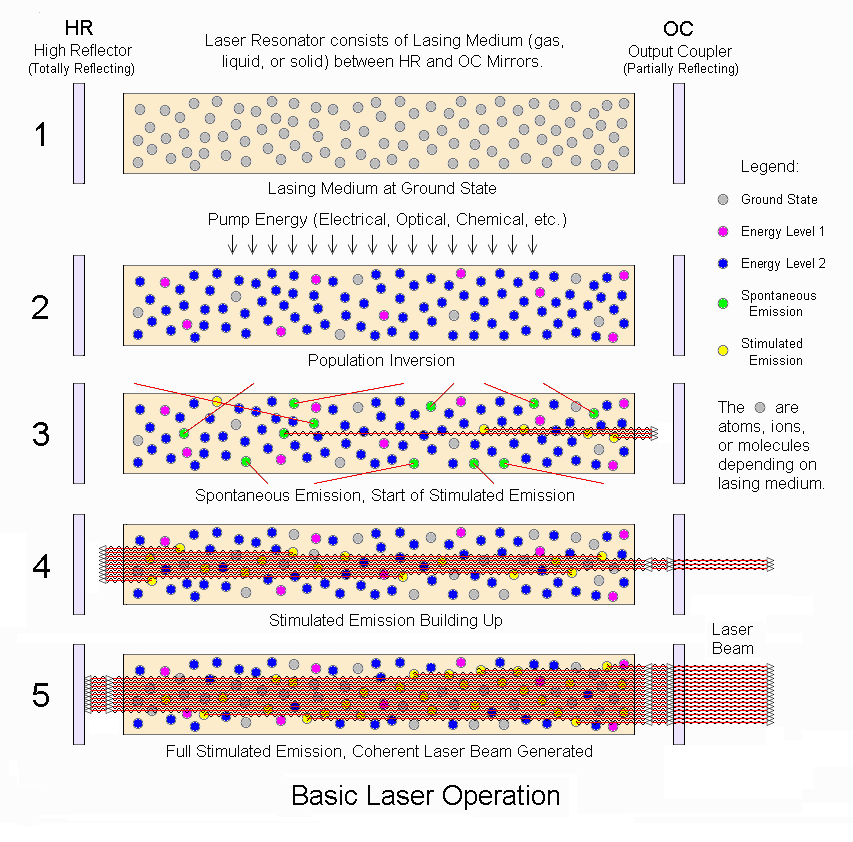
Laser Operation

Lots of info here: 

CO2 Info Summarized From Links

Gas mixture & its function:
13.5% N2 :    excited by gas discharge (pink glow) collides with and moves CO2 to level 3
9.5%   CO2: molecule that lases at energy level 3-2.
77%    He:    collides with CO2 at level 2 and then collides with tube walls for cooling
2%      H2:    gas discharge disassociates CO2 into CO and 02. H2 mixes with CO & O2 to regenerate CO2  

Ionization Voltage: 25 KV
Voltage at lasing:    13-15 KV
Negative resistance: 200-300K

Breakdown voltages

https://en.wikipedia.org/wiki/Dielectric_gas
https://en.wikipedia.org/wiki/Dielectric_strength

CO2: Air *.95
Air:  3,000,000 V meter

Laser Tubes

Synrad 40 W Lasers: Specifies a 100us rise time.

References To Aricles and Previous Work

https://en.wikipedia.org/wiki/Grayscale
Understanding CO2 lasers
Principles of plasma discharge
Dynamic PSpice Model of C02 Laser Tube
Gas Laser Electronics
Basic Laser Principles


-----------------
Enjoy and leave comments and discussion;

Maker Don

Tuesday, December 20, 2016

Engraving and PWM Control

Pulse Width Modulation (PWM) Control Considerations for Engraving

In RESEARCH PHASE

I have been thinking about the power scaling in my K40-S, especially as it relates to engraving applications.
After tromping for months through the Laser Power Supply (LPS) & PWM forest I came to some realizations that drove me to probe deeper into the PWM control of my K40-S.

I have not done a lot of engraving yet but expect that in order to get to rational and repeatable engraving quality exacting the smoothie PWM settings is important.

Donate:

Please consider donating (button to the right of this post).
Your donations help fund additional research, tools, and parts that I will return to the community as information. For other information on the K40-S build use the  K40-S BUILD INDEX with schematics.

------------------------------------------------------------------------------

Grey Shade Test Images


--------------------------------------------------------------------------------

Section 1: Laser Power Control Function

Lets first describe a simple digital laser power control function:
  • LaserPowerOut (watts) = SoftwarePwmDF(%) * LaserPowerMax(watts) 
where:
  • SoftwareDF = the PWM signal value [the software's PWM control output] as a percent that the pulse is ON relative to the period of the PWM cycle.
  • LaserPowerMax = the maximum power the laser can output
This means that the laser's power output will be proportional to the DF of the PWM signal if the LaserPowerMax is held constant.

How PWM power control works:

PWM is a schema for digitally controlling the power of a device by switching that device's power ON and OFF proportional to how much average power you want the device to output. Unlike analog control, the PWM signal has only two states, it is either ON or OFF.

Example: To make a 40-watt laser output 20 watts using PWM control, the software would turn the laser on 1/2 of the time and off for 1/2 of the time.

There are two important design factors in PWM control:
  • Duty Factor: the length of time the control is on during a given cycle or period
  • PwmPeriod: the time or period for one cycle of power control.  This is the time increment over which the PWM control is applied.
  • PWM frequency: The inverse of PwmPeriod is the PWM frequency.
Basic PWM definitions

For example: if the PwmPeriod is .016667 seconds that means that every .016667 seconds the power controller decides how long to turn on the laser, based upon the desired DF. In the case where we want to output 20 watts, the system would keep the PWM signal true for .008333 and off for .008333 seconds i.e. 50% DF.
Note: In this example the PWM frequency is 60hz.
  • PWMfreq = 1/PwmPeriod
-----------------------------------------------------------------------------------------------------

Section 2: Predictable PWM Control Is Important in Engraving and Grey-Scale Imaging:

It is important that the PWM control of the LPS be stable and predictable otherwise the power output at the laser will not reproduce what the software is expecting. Although this may not impact output quality when cutting with a laser it will have a large effect on the fidelity of engravings or other jobs where software control algorithms expect a linear PWM vs power output function.

When digital laser engraving, the darkness of the image is controlled by scaling power (the PWM signal) across the range of the laser's power output curve. Whereas 100% DF turns a 40-watt laser on at 40 watts, a 10% DF will turn the laser on at 4 watts. When engraving a grey-scale image the controller decides during each pixel time what power to set the laser at to get darkness that is proportional to other pixels in the image.

Note: A pixel time is a time that the laser is on to produce a digital bit of information. The pixel time is proportional to the resolution of the engraver and its speed across the surface.

In photography and computing, a grayscale or greyscale digital image is an image in which the value of each pixel is a single sample, that is, it carries only intensity information. Images of this sort, also known as black-and-white, are composed exclusively of shades of gray, varying from white at the weakest intensity to black at the strongest.[1]

The grey shade (from light to dark) control in a laser engraver is created by using increments of PWM DF values to create an increasing scale of intensity.

Therefore it follows that a given PWM value must create a predictable laser output power across it min to max range if high-quality digital laser engraving is to be expected.
As an example, if the controller sends the laser power supply a PWM value of 10% and the LPS subsystem does not output 4 watts then what the controller expects the image to look like and what is actually imaged, will be different.

Dithering

Just as an FYI, Dithering is a technique employed to create one bit black and white digital images from grey shade. Dithering does not employ stepped control of the PWM it rebuilds an image by using patterns of black and white dots.

Sources of PWM control errors:

Power control errors can occur in the K40 system if it is not electronically (PWM) controlled in a predictable manner. Traditionally the K40 LPS has employed digital control using one of two input controls; "IN" or "L".

"IN" control

The IN input is an analog input that adjusts the laser's power output proportional to a DC voltage on its input. The IN input is an analog control.
When connecting a digital signal (PWM) to the analog IN input two errors may be created.

For this explanation a traditional and worse case form of interconnection is considered where:
  • The PWM signal is a digital signal traversing 0-5VDC connected to IN.
  • The "Current Regulation" pot is connected from 5VDC to the ground with the IN signal connected to the center of the pot.

The driver (D) most often used in K40 conversions is a level shifter 

The Error

The PWM, in its high and low state, biases the IN pin at either 5VDC or ground. The proportion of the resistance of the pot to 5VDC vs the resistance to ground changes with the position of the pot. This configuration makes the value at IN for any given PWM and pot position a convoluted function of the PWM DC bias + the analog position of the pot. In this configuration IN is not a value that is known to the controller and the LPS is not accurately being digitally controlled.

When connecting the PWM to the "IN" pin the laser power function becomes:

  •  LaserPowerOut (watts) = SoftwareDF(%) * (RelativePotPosition(%) + (ErrorFunction)) * LaserPowerMax
whereas:
  • ErrorFunction = DCOffset + PotsLiniarityError
I have not modeled the ErrorFunction and decided it is not worth doing since there is a more reliable and predictable way of digitally controlling the K40's LPS. Even if we knew the ErrorFunction I doubt it could be implemented in the software control since the position of the "Current Regulation" pot is unknown to the controller.

Note: this is not to say using IN will not work. I do however predict that the use of IN, especially when the "Current Regulation" pot is installed, will result in irrational engraving results because of grey scaling errors created by power errors that are external to the controller's knowledge. The errors cited above may be adjusted out by "tinkering" with a combination of the laser power limits in the configuration files and the position of the "Current Regulation" pot. Ideally, we want a control system that does not require tweaking and creates predictable control.

Getting to a predicable power control schema does not remove the many other errors that effect engravings such as those created by the LPS, optical subsystem, and materials variations. It does however eliminate unnecessary control systems errors.

Predictable Digital Laser Power Control:

A better approach is to use the "L" input control signal. On some supplies this input can be found on the LPS DC connector and on others it is on both the DC connector and the center digital control connector. On other supplies, the equivalent of "L" is TH or TL.

The "L" or TL control is a digital input that responds ONLY to the ground to turn on the laser.

With a proper PWM signal connected to "L" and the "IN" line pulled to 5VDC (analog full on) the LaserPowerOut function becomes:
  • LaserPowerOut (watts) = SoftwareDF(%) * LaserPowerMax
You can see that this configuration eliminates all the control errors outlined above.

Note: Proper PWM control using "L" is to ground the "L" pin during the PWM's on period. An open-drain or open-collector is the best electronics circuit to use.

--------------------------------------------------------------------------

Section 3: The Laser is a Consumable: 

The laser in the K40 is consumable meaning that the power of the laser will decrease with use and time. This introduces another error in the digital control system in that LaserPowerMax will change over time. If the laser's max power decreases then the absolute intensity across a programmed greyscale will change. We need a way to adjust the overall intensity without changing the greyscales dynamic range nor relative values. This can be accomplished by leaving the "Current Regulation" pot installed in its stock configuration. This pot controls an internal power output vs current setting internal to the LPS unrelated to "L" PWM value.

Doing this changes our LaserPowerOut function to:

* LaserPowerOut (watts) = SoftwareDF(%) * (RelativePotPosition(%) * LaserPowerMax)

Now think of the "Current Regulation" pot as an overall Intensity Control. This configuration allows the max power of the laser to be a fixed adjustment while allowing the PWM to control the dynamic power within the range of (ReleativePotPostion * LaserPowerMax) values.

Configuring Max Power @ the Smoothie:

Another consideration in managing the K40's laser power is to limit the current to 18ma max. Even though some lasers can output more than 18ma it is not recommended to run them above this level because this can reduce the laser's life. However, the light power output @ 18ma will change as the laser ages and therefore the power supplies "Intensity" setting will need to change to keep the same light output at 18ma.

Configuring laser power in the smoothies configuration file three things can be controlled:

An example set of  a typical smoothie configuration:
laser_module_maximum_power                   .8         
laser_module_minimum_power                   0.0         
laser_module_default_power                        0.3                        
laser_module_minimum_power                   0.0            
laser_module_default_power                        0.3        

Without a manual "Intensity" control to insure the laser does not exceed its 18ma limit under PWM control, the smoothie configuration would need to change as the laser wears.

Example:
1. Putting the "Current Regulation" pot at max and pressing test resulted in a current = 24ma
2. Since we do not want the laser to run above 18ma we need to set

  • laser_module_maximum_power = 18/24 = .75 

After 6 months of use, the current at max pot position now reads 19ma. Therefore we need to reset

  •  laser_module_maximum_power = 18/19 = .95 

With the "In" + "Intensity Control" installed as explained above the Smoothie's configuration file would not need to change. Adjust the "Intensity" knob so that when the "Test Switch" is pushed the laser does not exceed 18ma. As the laser wears the actual position of the "Intensity" knob will migrate clockwise yet the configuration file will not need to change. At the point that the current cannot attain 18ma at the max intensity position, the laser may need replacement if you want the same level of darkness in an engraving.

This is how I would configure the Smoothie's control:

laser_module_maximum_power                   1.0         
laser_module_minimum_power                    0.0         
laser_module_default_power                         0.3                          
laser_module_minimum_power                    0.0         
laser_module_default_power                        0.3            

--------------------------------------------------------------------------------------------------------------------

Section 4: Finding the PWM Period for Optimum Engraving

What should the PWM period be set to for the best engraving?

Design requirements:

  • The time that the laser controller has the opportunity to turn the laser on/off during writing a pixel must be <= the time it takes the gantry to traverse that pixel. Otherwise, there will be a loss of resolution.
  • To apply full power to a pixel the power would be held on for a full pixel time, for 50% power it would be held on for 1/2 a pixel time, and so on.
  • Ideally, the period of the PWM should be much shorter than a pixel time so that multiple PWM cycles can have the opportunity to control the power within a single pixel time. We will call this PWM Control Resolution and it is defined as the # of PWM control cycles in a pixel period. I don't know what the minimum practical value for PWM Control Resolution would be because it depends on the ability of the PWM to be synchronized with a pixel time. The theoretical value is 1 if there are no synchronizing errors between the PWM assertion and the pixel generation.  A more safe value is at least 2.  A 10x factor would likely eliminate any errors caused by this factor.
The relationship between Pixel time and PWM period.

The K40 PWM Model

The optimum setting for PWM is dependent on multiple interacting factors making choosing the PWM period a complex exercise. Therefore a model has been constructed that calculates a range of key values based on these inputs:
  • Image resolution (DPI):
  • Laser response time (us);
  • PWM Control Resolution # of PWM cycles (per pixel period);
  • Gantry speed (mm/sec):

What-if Scenario #1 Laser Response = 20us

Table 1: PWM periods @ 20 us laser response

Understanding the Models Output:

The red areas indicate unacceptable operating points
The white areas indicate acceptable operating points
Axis definitions; 
  • Top and bottom X = various PWM periods
  • Top table Y = gantry speeds (mm/sec)
  • Bottom table Y= 5% increments of grey shade in 

Table 1 Inputs:

  • Image resolution (DPI): 360
  • Laser response time (us); 20
  • Threshold # of PWM cycles (per pixel period); >=1
  • Gantry speed (mm/sec): 300

Reading Table 1:

Pick a column in the top table and read downward until you encounter a red cell. This is the point at which the # of PWM cycles falls below the threshold.
Keep scanning down the same column into the bottom table until you encounter another red/white cell intersection. This is the point at which the PWM pulse width is slower than the response time of the laser. 
Acceptable operating points are at the intersection between white and red cells. The operating parameters for that point can be found as the x row and y column labels for that intersection.

Finding an acceptable operating point is a combination of the top table and bottom table. The ideal operating point(s) is a column(s) in the bottom table that is fully white across the 100-5% range, meaning that the laser can respond to each of those grey shade steps.

Interpretation of Table 1:

In the top table @ the column labeled 200us move down to the row corresponding to 300mm/sec which contains a white cell of 1.18. This means that there are 1.18 PWM periods in a pixel time of 200use for a speed of 300 mm/sec. That is larger than our input threshold of 1 which is why it is white.

Continue down that column and look for a red to white transition in the bottom table. We find that at the row labeled 10% and the value in that cell is 20us which is equal to the laser response time we input to the model. The next cell below is white with a value of 30us which is larger than the laser's response time. This means that the laser may not respond fully and expose the surface if the PWM DF is set <=10%.

What is the optimum PWM value(s) suggested by Table 1

The default PWM period value of 20us (column 2) in the smoothie configuration table will not enable quality engraving if the laser response was actually 20us.

A better range of configuration values would be a PWM period of 200us to 400us.

What-if Scenario #2: Laser Response = 2us

Table 2: PWM with 2us laser response time
The laser response was set to an order of magnitude faster and the results of scenario 2 show that the system would engrave across the greyscale for PWM period values >= 40us.
At a PWM period of 20us, the engraving would be marginal for PWM DF values of less than 15%.  

-------------------------------------------------------------------------------------

Section 5: Smoothie Configuration Settings:

Default Smoothie Values

So what should the Smoothies PWM period be set to? The default in my configuration was:
  • laser_module_pwm_period                      20  (in micro-seconds)
The modeling exercise above suggests that 20us is not a good choice for a PWM period. At the slower laser response value, it would produce poor engraving across the entire range and at the faster laser response, it would be marginal at the lowest 2 shades of grey.

Marginal PWM Control Resolution with Excellent Grey Scale Reproduction

If we assume the fastest laser response measured so far (Table 2) and stay within the K40 specifications of 300 mm/sec, a PWM period setting of 200us period would allow marginal PWM Control Resolution but perfect grey shade reproduction. 
Consideration: I am not certain if PWM Control Resolutions >1 are important to K40 engraving quality.

Good PWM Control Resolution with Excellent Grey Scale Reproduction

Slowing the speed to 100mm/sec @ a PWM period of 200us would improve the PWM Control Resolution almost 3x and still produce perfect grey shade reproduction. 

Recommendations for Engraving Settings

Start your engraving evaluation with these settings using a grey shade test pattern.  
  • PWM period = 200us
  • Speed= 300 mm/sec
If the quality is not acceptable independently try the following, while retaining the above PWM settings;
  1. Adjust the max power until you find an acceptable level at the lowest grey shade
  2. Lower the speed below 300 mm/sec until you find an acceptable level
  • Try combinations of the 1&2 above

---------------

Section 6: ToDo's 

  • Continue to test the response of the laser under various pulse widths to determine practical values.
  • Test using grey shade scales, a series of model input values to validate the model.

Appendix A: Sources of Model Input

Laser Response

There is no point in setting a PWM pulse duration less than the laser's ability to respond! If at the lowest PWM DF the resulting pulse is shorter than the response of the laser it will not turn on or at best will not reach full power during a pixel time. As an example, with a 20us PWM period, the pulse time of the PWM at 5% DF is only 1us. If the laser's response time was 20us this pulse would not even be realized.

The effect of the response of the laser


Key Question: 
How long does it take the laser to ionize and get to full power after it is digitally told to turn on? 

Research information:

Tests were done in the PPI community use pulse duration's of:
  • Minimum PPI Pulse Time: 3-4ms or .003-.004 seconds
  • For reference this frequency = 250-333hz
From its use in successful PPI implementation, I would assume that a laser can respond at this rate. However, this is 3 orders of magnitude too slow for our engraving example (see calculations in Appendix B).

Laser Response Testing :

The following summarizes tests I conducted in an attempt to characterize the 40-watt K40 laser response.

Test Approach

Measure the rise time of current in the laser cathode circuit as an indirect method of determining the laser's response time. The test makes the assumption that the laser's light output rise times are similar or faster than electrical rise times. This approach is being used after attempts to measure the actual laser's light output failed. Reasons for failure include:
  • Standard digital sensors have no response in the far infrared (10600nm)
  • The power at the output destroys most sensors
  • Pyroelectric devices have long response times.

Test Setup:

  • Oscilloscope channel 1: in the lasers cathode circuit, @ the current meter on the control panel
  • Oscilloscope Trigger: Test button closure

Channel 1: Cathode current rise time = 1.84us

Channel 1: Cathode current rise time = 1.9us

Channel 1: Cathode current rise time = 20us

  Channel 1: LPS internal PWM.   Period = 408us

Test results

  • Rise times in the range of 1.84 to 20us were measured. 
  • There is evidence that rise times of < 2us are possible.
  • The LPS internal PWM is 408us. This may be an indicator of what the manufacture felt was a good PWM period for the K40. 
    • Referring to the model above 400us allows only .59 PWM cycles @ the rated 300 mm/sec. 
    • A related consideration is that stock K40 does not engrave with grey scales instead the image is dithered. Therefore small variations in PWM synchronization may not be visible. 
    • It is also possible that this is an error in the stock K40 that was not addressed
More testing is needed to rationalize and verify the relationship between cathode current and laser output responses. In the meantime these values will be used in an effort to "what-if" model K40 engraving operating ranges (see the model above).

Appendix B: Specifications and Calculations 

Stock K40 specs:

  • MAX: 600mm/S 
  • Carving: 7mm/S 
  • Cutting: 0.5mm/S 
  • X-Axis Motor: 0.33A/Phase 
  • Y-Axis Motor: 0.44A/Phase

Technical Parameters:
Interface to Computer: USB Port
Tube Trigger Volt: 20KV;Tube Operating Volt: 15KV
Current:0~22mA
Engraving Area: 260x180mm
Maximum Item Size to Engrave: 10.25W x 8.75L x 2.85H in (260mm x 220mm x 70mm)
Laser Tube (life hours): 1000-1300 Hours
Laser Power: 40W
Engraving Speed: 0-13.8 in./s (0-350mm/s)
Cutting Speed: 0-1.38 in./s (0-35mm/s)
Minimum Shaping Character: 0.04 X0.04in (1mm X 1mm)
Resolution Ratio: 0.001 in (0.026mm) / (1000dpi)
Resetting Positioning: 0.0004 in (0.01mm)
Software Supported: MoshiDRAW software (both NewlyDraw and NewSeal function)
Power Consumption: 250W
Operating Temperature: 32-113F (0-45C)
Recommended Spare Parts/Consumables: Laser Tube, Focal lens, Reflection lens
Voltage: 110V~240V
Frequency: 50Hz~60Hz


Example Calculations for Typical Engraving Configurations:
Assumptions:
  • Image Resolution (DPI): 360
  • Grey-scale increments (%): 5
  • Gantry speed(mm/min): 1500-1800
  • Gantry speed(mm/sec): 250-300 
  • Gantry speed (inch/sec): 9.84 - 11.81 inch/sec [K40 machine specification says: 13.8 in/sec]
  • Time to move one inch: .1016-.085 sec/inch [101.6 - 85 ms]
Calculated values using assumptions:
  • MinPixelPeriod: (.085 sec/inch) / (360 pixels/inch) = .000235 sec/pixel = .235ms/pixel [235us]
  • PWM frequency(hz): 4251 [4.251 khz]
  • PixelPeriod: 235 us

Simple formula for calculating MinPixelPeriod: 

  • MinPixelPeriod (us) = 1524000000/(speed (mm/min)) * DPI)
Example: 1524000000/(1800 * 360) = 1524000000/6480000 = 235.18

Links to Related Posts

References to More Information and Previous Work

https://en.wikipedia.org/wiki/Grayscale
Understanding CO2 lasers
Principles of plasma discharge
Dynamic PSpice Model of C02 Laser Tube
Gas Laser Electronics
Basic Laser Principles


-----------------
Enjoy and leave comments and discussion;

Maker Don

Sunday, November 6, 2016

K40-S Laser Power Supply Control "Take 2"

K40 Laser Power Supply (LPS) Control

During my journey to convert my K40 to Smoothie control I and many others have been frustrated trying to find a reliable, predictable and understandable means to digitally controlling the K40's laser power. For history see my previous post which I am superseding with this one.

http://donsthings.blogspot.com/2016/06/k40-s-laser-power-control-interface_86.html

CAUTION: LASERS AND THEIR HIGH VOLTAGE SUPPLIES ARE BOTH ELECTRICALLY LETHAL AND OPTICALLY DANGEROUS. THEY HAVE THE POTENTIAL TO KILL AND/OR BLIND YOU

STAY AWAY FROM THE HIGH VOLTAGE SUPPLY'S OUTPUT!


WEAR PROTECTIVE EYE WARE AT ALL TIMES WHEN OPERATING A K40!


DO NOT OPERATE A K40 WITHOUT THE PROPER LASER INHIBITING INTERLOCKS INSTALLED AND OPERATING PROPERLY!


BY READING THIS POST YOU AGREE TO USE THIS INFORMATION AT YOUR OWN RISK!

Donate:

Please consider donating (button to the right of this post).
Your donations help fund additional research, tools and parts that I will return to the community as information and how-to's. 

Simple Smoothie PWM Control 

A simple diagram showing how to connect to the LPS PWM from a smoothie 5x. You only need 2x wires.


NOTE ON CONFUSING LABELING:

In general, driver MOSFET's outputs on Smoothie compatible boards are labeled [+ or VBB] and [- or gnd]. 
The +/VBB is connected internally on the board to a [+] power source it is not a signal. 
The [-/gnd] is connected to the DRAIN of the MOSFET (not ground). 
For open drain connections you want to be connected to what may be marked [-/gnd] pin.  Pick up an actual ground for that signals cable from another pin (like the picture above).


You can remove the pot and install the red jumper which allows the PWM to have full control. I do not recommend this configuration. Although you will have full software control of power you will have to regularly calibrate your machine for max power. See Setting " Power Calibration"

Leave the Pot in

I recommend this approach!

You can elect to keep the "Current Regulation" pot installed in its stock configuration. If you do the actual laser power will be the product of the pot setting AND the PWM setting.

I.E. if the pot is set for 50% power and the PWM is asking for 50% power then the actual power will be:

Actual Power = Current Calibration % * PWM duty cyle

Example: Pot set a 50% and LaserWeb asking for .25%
Power = .5 *.25 = .125 or 12.5%

If you leave the pot in you can allow the software to control the power within its min - max range (0-100%) that the pot is set to. The Pot becomes an overall intensity control and you do not have to calibrate the machine for MAX power.

See this developing post for more detail regarding the PWM configuration effect on engraving:
http://donsthings.blogspot.com/2016/12/engraving-and-pwm-control.html

Actual photo of how my machine is wired


Power calibration

I do NOT recommend taking the "Current Regulation" POT out.

Its my expectation that you remove the pot and pull the IN to 5vdc or set the "Current Regulation" (IN) to full on you will need to calibrate the power settings in your K40-S to keep the power range below the 18ma max operating range.

Power settings and verification

I have not completed the testing on this process but figured those looking for precision control of power would value having a preview. This is less important when cutting than when engraving or carving.

I recommend running a grey scale test and if that images but does not look good I would suggest something is wrong with your settings not your connection to "L".

When using the L line for normal operation with a pot installed you should have it set to a position that limits the current to 18ma and let the controller vary the power within that range. If you have the pot removed and the IN line jumper-ed to 5VDC you have to insure that the driving software never exceedes the max 18ma current level.

Setting the max power

If you are set up right the controller will not exceed the limits set in the configuration and you will not exceed where you want the tube to operate i.e less than 18 ma.

To calibrate:

  1. Verify your max power by using the test button to find out what the max current is with the pot full on. Example: your current meter at max pot setting = 24ma
  2. Then calculate what % you want the max limit of be and set that in the configuration file. Example: 18/24 = .75. You want the max power that the controller ever asks for to be less than 75%.
I advise testing by sending G codes for various power levels and verifying that it stays within limits on the current meter ("Current Regulation Pot"). Make sure the Gcode keeps the laser on long enough to get a good reading on the analog meter.

[later I will post a test for this]

After this is set up the controller should have full control of the power while keeping the power below the 18ma limit. 

You may need to re-calibrate as your laser wears and power levels drop.

Note: this approach to Max power setting may reduce your software's dynamic range for engraving. That is why I do not recommend setting the max power this way. 

See: http://donsthings.blogspot.com/2016/12/engraving-and-pwm-control.html for further development and research.

-----------------------

The remaining sections provide design and engineering information

Thanks for help from these folks .....

Thanks to +Paul de Groot and +Kim Stroman  for providing a schematic and broken power supply, respectively, as a source of information.

Multiple versions of LPS

We now know that this confusing situation is exacerbated by the existence of multiple versions of LPS's that are in use. Many look the same externally but are different internally.

You cannot tell what type of supply you have by any external means ... that I have found.

Below are pictures of  three few supplies. We have a schematic of Pauls and Kims. Mine I can only poke from outside because it is in service.

Caution: I know there are other versions of LPS out there and this analysis applies to the ones shown in this post. I will add the others as I get samples to trace.

Donate your dead LPS to research

If you have a dead one that you want to donate to this research email me at:

don_kleinschnitz@hotmail.com

PS designation

For this post I am creating a designation for these supplies. To date I have found 3 types and I designated them like this:
  • First letter: the color of the AC power connector
  • Second letter: the color of the control connector
  • Third letterL the color of the DC power connector
  • Third letter: the color of the Power-on LED

Green-Green connectors with Red power LED

Designated G-G-G-R in this post
Photo:
+Paul de Groot's supply

Green-Green with Green power LED

Designated G-G-G-G


+Kim Stroman's supply. Note: flyback disconnected

Green-White connectors with Green power LED

Designated G-W-W-G
My K40 LPS

More LPS style and interconnect references

Schematics:

For G-W-W-G style supply: 

LPS schematic PDF

LPS schematic download (.sch)

For GGGG style:

A share-able schematic that is a work in progress...

PWM circuit sketch not in main schematic yet
PWM circuit

For the G-G-G style supply here are some simplified schematics of the input controls:


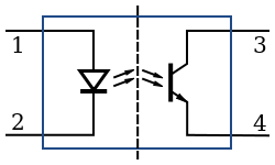
Note that for HV isolation the "ENABLE" and "L" inputs to the LPS are routed through opto-coupler's. The external control signal simply provides a ground to the cathode of the opto-couplers transmitting LED to operate.
In the case of Smoothies open drain control (see PWM Control Via L, below) the opto-couplers LED is connected to the FET's drain and when the FET switches on current flows in the led illuminating it, correspondingly turning on the receiver transistor.


LPS control theory of operation

Although we are not yet finished understanding how external controls are implemented internally on all LPS versions we suspect that from an external perspective the fundamental behavior of these controls are the same.

In general the LPS is switched mode AC-DC supply that controls current with Pulse Width Modulation that drives a flyback arrangement and voltage multiplier. This supply creates a regulated and very high voltage.

AS I NOTED ABOVE: THESE SUPPLIES OUTPUT LETHAL VOLTAGES.

So as to minimize confusion; in a K40 conversion there are two PWM functions at play. The one that is asserted by the digital controller (like a smoothie) and the another that is employed inside the LPS using a PWM IC. These LPS's are designed to operate both stand alone and with a remote means of controlling the level of power.

IMO: When a digital controller is providing PWM control the internal PWM is redundant.  

Basic control function behavior

There are three fundamental control functions on these supplies that are sometimes referred to by different names. I will give them a generic name for this post and also associate them with their real names where I can.

ENABLE: 
The "ENABLE" signal controls the internal PWM controllers output. If Enable is not asserted the laser will not fire because the internal PWM's Duty Factor (DF) is either 0 or in alternative implementations its output is disabled.
  • Ports that behave this way are: TH,TL, K.
At least two ways have been found for how this control is accomplished.
  1. Enable is connected through an opto-coupler that when asserted* enables the output of the internal PWM generator. If enable is not asserted the PWM generator is disabled.
  2. Enable is connected to an opto-coupler who's output transistor is connected to a differential amplifier.  When enable is NOT asserted* it biases one leg of  the amplifier insuring that the IN voltage will not generate a PWM DF > 0. If enable is asserted* the PWM DF will proportionally follow the IN voltage. 
*In all cases opto-couplers in these LPS are digitally asserted by grounding them. These signals are internally connected to the cathode of the opto-couplers transmitting LED.

FIRE:

The FIRE signal enables the output of the internal PWM to run if asserted and remain off if not.
  • Ports that behave this way are: L and Enable #1 above. 
In all the supplies above we have found that FIRE is always accomplished this way:
  1. Connected through an opto-coupler that when asserted* enables the output of the internal PWM generator. If FIRE is not asserted* the PWM generators output is disabled. 
Note 1: The internal "Test" button on the LPS motherboard is connected to this signal through an isolation diode.
Note 2: You will notice that this configuration of FIRE is exactly the same as #1 Enable behavior above. In some supplies it seems that there is an AND function of Enable and FIRE that controls the output of the PWM generator. [more verification needed here].

Power Control (PC)

The PC signal is the means by which the LPS power can be controlled with an analog signal. This signal can be in the form of a variable voltage from a pot or an analog voltage from a remote controller. 
To add to the confusion PC can be overloaded by a digital signal of the right voltage making the IN a power ON-OFF function. More on this further down. 

IMO: this control was not intended to be a digitally controlled input. That is in spite of the fact you will find many configurations and vendors that promote using it as PWM control. 
  • Ports that behave this way: IN
At least two ways have been found for how this control is accomplished.
  1. The IN signal adjusts the current through an opto-couplers input LED whose receiver provides a corresponding and proportional voltage to the PWM generators DF control. This IN signal is isolated and connected to the cathode of the coupler's input diode. In this configuration the IN signal expects a resistance to ground that changes the current in the opto-couplers LED transmitter and correspondingly changes the current in the output transistor. Its note-able that the opto-couplers used in this analog mode and the ones used in a digital mode* are the same component part. The only operational difference is how the current through the diode is provided.
  2. The IN signal is directly connected to one leg of  the internal PWM controllers differential amplifier. When enable is asserted this amplifiers output follows the IN signal adjusting the internal PWM's DF and in turn the output power. When enable is not asserted the other leg of the amplifier is at large enough voltage to prevent the amplifier from outputting a voltage proportional to IN effectively creating a PWM DF of 0. In this configuration the IN signal is not opto-isolated from the supply.
----------------------

Putting LPS PWM control into practice on a K40 conversion

The current investigation and its corresponding espoused theory provide a basis for effectively using PWM control in a K40 conversion irrespective of a specific supply's actual internal operation.

The challenge with defining the RIGHT and WRONG way to configure PWM control of a K40 LPS is that you can make multiple approaches work. The fact that there are multiple unrecognizable versions of these supplies does not help matters. 

Therefore to start with I am going to define how I plan to use the information provided above. Then when I complete building and testing it I will update this post. Other configurations than the one outlined below may work. Its my judgement that the one below is the simplest and most reliable.

Interlock control: 

Leave the stock wiring for the "Laser Switch" and insert in series with this circuit any additional interlocking functions including cover switches and temperature monitors. 

PWM control via 'L":

Connect the controllers PWM function through an open drain (OD) or open collector (OC) to the L pin. Choose a transistor that is connected the controllers PWM function. Insure that in your controller you configure the input to this transistor to assert in such a way that the transistor provides a ground. In other words, when PWM from the processor is TRUE the transistor should be turned on. This transistor is connected to the L pin without any form of pull-up or level shift-er. This pin from the controller will be isolated from the LPS.
In the supplies we tested this signal can be found on the rightmost pin in the LPS DC connector.

A typical Open Drain configuration

The equivalent circuit of the K40-S PWM connection
IN:

Since we are providing digital power control to the LPS through "L" we do not need another form of power adjustment for PWM control but we do for max power setting.
As the laser wears the current required to get the same power changes so the power ranges changes .
Certainly we can change the max-min ranges in smoothies config file but why go through that annoyance.
Leave the pot in and it functions as an intensity control (see Power Settings and Verification above) 
However recognize that the controlled power is the product of the pot setting and the Smoothie PEM setting.
Therefore if the controller is set at 50% and the pot is set at 50% the actual power may be (.5*.5) or .25%. This is because the controller is turning ON the LPS whose power is fixed at 1/2,  1/2 the time .... is that sufficiently confusing :).

More detail at these posts:
http://donsthings.blogspot.com/2016/12/engraving-and-pwm-control.html

Level shift-er use:

It has become common practice to use a level shift-er connected between a 3.3vdc PWM controller signal and either the IN or L signal on the LPS.
I believe that this configuration can be made to work but creates a level of complexity that is unnecessary. Most controllers have Open Drain or Open Collector drivers available. These are less complex to configure and wire and use less parts.

When an OC/OD is not available:

If there are no OD/OC outputs available I would use a discrete circuit that connects to a processors 3.3vdc signal to (R3) and connect "L" to the collector of Q2. Remove R4.

To test this setup. Before you connect to the LPS leave R4 in and connect this circuit to the controller and look at Q2 collector with a scope.  Insure that the collector of Q2 is being pulled to ground with the assertion of a PWM pulse.

I do not plan to test this configuration.

A level shifter circuit I found on the web (untested).

PWM on "IN" with pot installed:

I do not recommend connecting a PWM  control to the IN with a control pot installed. Unless the pot is left in the full power position you will create a complex condition where the incoming PWM is combined with the bias the pots wiper provides. This configuration creates IN bias values that change with the pot position.

PWM on "IN" with no pot installed:

A 0-5vdc PWM signal can be connected to the IN pin without a pot and operate properly. I don't see the value in using this approach as the configuration I recommend gives you the option to keep or discard the pot while providing opto-isolation. This configuration will also require constant max power calibration and configuration settings changes. 

Testing:

The first step was to install the "Simple PWM control" and test its function.

Test the following:

  1. With interlocks open
    1. The laser does not fire with "Test" and/or without the PWM present.
    2. The laser does not fire when the machine is powered down or powered up
    3. The laser does not fire when the smoothie (controller) is reset
  2. With interlocks enabled:
    1. The laser fires when PWM present
    2. The laser does not fire when PWM is not asserted.
    3. The laser does not fire when the machine is powered down or powered up with PWM not present.
    4. The laser does not fire when the smoothie (controller) is reset
  3. The PWM duty factor is controllable from the SMOOTHIE

Signal quality and polarity

Note tests done on a G-W-G supply

Pict#1
Top: PWM from Smoothie
Bottom: PWM at the "L" pin

Pict#2
Top: PWM from Smoothie
Bottom: current in LPS
Pict#3
A table of measures


Above are some scope traces verifying the configuration:

  • Pict#1: The signal looks good and the "L" pin is being driven to the correct levels with the correct polarity.
  • Pict#2: My first try at correlating laser output with PWM. At first glance I am not convinced that the laser is responding properly to this freq of PWM. More testing needed to draw any conclusions.
  • Pict#3: Smoothie PWM with measurements table.
Note: these tests were run using the GLCD "LASER" functions to set and run PWM values.


Index of LPS types

For reference I am including pictures of these PS layouts and packaging.

G-G-G-R:


G-G-G-G


LPS Album

Laser Power Sources

Theory of laser power sources
Enjoy and comment,
Don