INSTRUCTIONS:

Check out the new MoBeam posts! To find K40 conversion information use the "INDEX", "SEARCH" or "LABELS" sections in the sidebar.

Sunday, November 25, 2018

Optical Alignment Tools Working Well

The optical alignment tools are a success

Based on the results of the "Santa Cookie Plate" project I gauge the new alignment to be a success.
I don't plan on doing more documentation or design iteration on the alignment tools unless the community request it.

There are 4 posts that pertain to improving optical components and alignment:
Improving mirror #1
Improving mirror #2
K40 optical alignment tool theory & design
Using K40 alignment tools


Enjoy and please comment
Don

Wednesday, November 21, 2018

K40 Alignment Tool Use

Reading the Tea Leaves

DRAFT VERSION 11/21/19

In previous related posts I outlined the upgrade of mirror 1-2 mounts and introduced a set of target holders intended to make optical alignment simpler.

There are 4 posts that pertain to improving optical components and alignment:
Improving mirror #1
Improving mirror #2
K40 optical alignment tool theory & design
Using K40 alignment tools

In this post I will show the results of my first tests while outlining how these tools are intended to be used for aligning your K40.

Donate:

Please consider donating (button to the right of this post).
Your donations help fund additional research, tools and parts that I will return to the community as information.

Introduction to alignment with the KlineWorks K40 Tools

This concept can seem pretty complex at first but with a little study it becomes intuitive.
The motivation to build the K40 alignment tools came from the notion that to properly align an optical system the beam position throughput its path needed to be seen in three dimensions. The diagram below illustrated that concept. 

The idea is to move graduated targets along the axis of the beam referenced to a surface that is the same as the axis the laser head is referenced to.

Reference Surfaces

In the K40, these references are the Y axis gantry and the X axis gantry. Once the target holders are made the reference surface can be ignored as the targets are placed into their holders and the holders are sitting referenced to the Y and X gantries respectively.

Z Position

The Z axis is represented by the placement of the target along the beams path. We will use the following nomenclature to identify values @ various positions:

x,y = [x position on target], [y position on target (from the targets reference point)]

(axis)(position #); where [axis = either X or Y], [position # = the # representing the targets placement along the optical path]
example: X(3) = 22; [the x value of a target placed @ position #3 = 22]

Targets Holders & Targets

The targets are graduated and held to the reference surfaces with in a slot. Since the target holders position the target accurately to a reference we simply need to analyze the difference in a beams placement on the target from one Z position to another. The targets are moved along the Z axis, burned and then the position in X & Y on the target shows the error in the respective axis.  

Example Interpretation

The target samples shown below are from position #1 and position #2 along the Y gantry axis. Lets examine what they are telling us:

Describing The Target Artifacts

First off lets define the static artifacts of the targets:
  • The graduated side of this target is facing the front of the machine 
  • These light graduations are 1/8" (.125") resolution and the dark are groups of 5 @5/8 (.625).
  • The right side is a reliable place to count X position from
  • The bottom is the reference to the Y gantry and is a reliable place to count Y position from
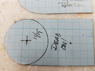
  • The circle is a rough representation of where the burn will show up. Note this circle is not intended to be accurately placed around the proper center position of the beam. It is for a visual reference only. However it looks like I got pretty close.

Reading the Error Between Two Positions

Position #1

Counting from the right to the burn mark we can set the X1 position to 21 graduations
Counting from the bottom to the burn mark we set the Y1 position to 17 graduations.
The burn @ target position #1 is therefor x,y = 21,17

Position #2

Using the same counting method as position #1 we can set the beams position at position #2 x,y = 20, 17

So what does this mean?

X1 = 21, X2 = 20: this means that the beam is travelling from left to right [as viewed from machine top] as it exits position 1 and hits position #2. In the X plane it is travelling at an angle of 1/8" over  about 8.5". We could calculate the angle but that would only have academic value. 

Y1 = 17, Y2 = 17; this means that the beam has no error in the Y direction :)! Meaning as the beam traverses from position #1 to position #2 it is has no up[toward top of machine] or down[toward bottom of machine] error. It is moving parallel to the Y axis of the machines gantry.
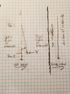
A visual representation of the error


What would I correct?

Lets keep this simple though. Instead of trying to visualize all the axis described above all one needs to know is that the beam is not perfectly straight and adjustment if any should be in the -X direction on mirror #1 without any change to the Y.
A simple approach to viewing the error, is to overlay one positions target over another. Then mark the second charts hole onto the first target showing the error. 
When viewed this way the error is simple to see and in actuality the beam is moving slightly to the right and slightly down. The difference in what you see here and the X/Y positions I counted above is the resolution of the graph.
Looks like the actual error in X and Y is closer to 1/16" over 8.5 ". The error is z,y = .0625,.0625


A Total Alignment Scenario

Lets take what we have learned from above and apply it to a total alignment. Lets examine the beam from mirror #1 to the materials surface. Lets make the entire optical path appear linear by laying all the burned targets into a line. Yes we are changing axis as we move down the Y gantry and fold to the X gantry but for alignment purposes we will just watch the error from one target to the other.
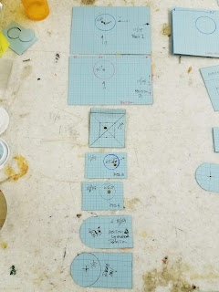
All targets positioned vertically...

Before going on to the next section zoom in on the above photo and orient your thinking. 

Mirror #1 position

No target avail for this one yet.

Mirror #2 Position

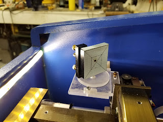
The target for mirror #1,2 are different than the other targets. They hang on the mirror and intent to show where the beam is hitting relative to the mirrors center. The target is registered to the left mirror mounts surface and a box defines the mirrors aperture [which is actually round].
We see that the beam is hitting in the upper left quadrant of the aperture about 1/8 above and left of center. 
Since the beam coming from mirror 1 is actually moving slightly down you would expect the beam to hit the mirror below the center. My guess is that the reason it is hitting mirror #2 high is that one or both of  the homemade mirror mounts [#1,#2] are vertically not exactly in the right position vs where it should be, after all I did guess at the dimensions. 
Since the beam coming from mirror #1 is pointing slightly down (1/16) I should lower that mount and then tilt the mirror up (1/16) until it hits center on mirror #2 ... Remember that a small change in mirror #1 position will be quite large by the time it hits mirror #2.
This is a good example of how these targets show what is really going on. 

For the X error if I tilt mirror # 1 to the right [as seen from the back] I should be able to straighten the path and hit mirror # 2 in the center.
Or call this good and move on :)


Target Position #3

Target position #3 is the leftmost position on the X gantry. This will capture the beam as it exits mirror #2 and proceeds to mirror #3.
A different target holder is used that straddles the X gantry and is fixed in place with a thumb screw. This holder uses a smaller target that is referenced to the bottom and right of the holder. 
Keep in mind that the circle is a rough approximation of the area where the beam may be and is simply a visual reference. The center of this circle is not the center of the objective head's mirror.

target at position # 3 xy= 4.5, 5 [error in annotation on chart]
We see that the beam is in the lower right quadrant of the relative circles position. At this point its position is interesting but not informative.

Target Position #4

The beam hits the target at xy= 5.5, 6.5. This tells us that the beam is reflected off mirror #2 at an angle that is left-upward i.e. up and toward the back of the machine. The beam from mirror #2 to mirror # 3 is not straight. 
Although the circle does not exactly represent the center of mirror #3 I suspect that its real center is pretty close. I am guessing that the beam is hitting mirror at an angle and slightly +X.  


Mirror #3 Position

I am going to add a target placed on the mirror #3

Position #4

Position #4 is the hardest location to get aligned but also the most important. As the beam hits mirror #3 and is reflected at a fixed 45 degrees it must enter the center of the objective lens. If the beam is not perpendicular to the surface and in the center of the objective lens it will exit the lens at an angle and hit the side of the lens mount or air assist nozzle. The the only adjustment on head is the rotation of the entire head which can effect the centering of the beam on the lens.
The final target is placed into the tube target holder and slid over the heads cylinder. The intention is to see if the beam exits centered relative to the cylinder. 
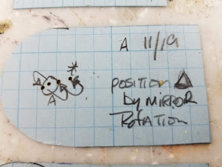
moving the beam by rotating the head assembly
At first try the beam hit well off center (the*). I rotated the head which resulted in moving beam (see series of dots) until it was in the center. 
Replacing the target with a fresh one and re-burning shows that the beam is in the center of the objective lens's area.
While writing this post I realize that the beam can be in the center at a certain point at the surface but still not be perpendicular to the surface. I need two point along the beam as it exits the objective lens. If we don't prove the beam is perpendicular the beam can be at a different center line for differing focal lengths.

Next Steps:

  • Test for stability; how long will an alignment hold with the new mounts.
  • Add a target on mirror #3's mount and accurately position its aperture.
  • Add another target position after the objective lens.
  • Investigate a new head design that allows for adjustment of mirror #3.

Summary so far

Evidence is that these tools and associated alignment technique work to visualize errors in the beam as it traverses its intended optical path. Is this a more accurate and simpler method than just putting targets on mirrors? Time will tell but for me this adds definitive measurements and better visualization of how the optical path traverses the machine.  Early evidence suggests that it will result in more accurate alignment especially for the more complex problem of laser replacement.

Enjoy and comment,
Don


Monday, November 12, 2018

Introducing Alignment Tools for the K40

K40 Optical Alignment Tools Theory & Design

Anyone that owns a K40 dreads the optical alignment process because:

  1. The mirror adjustments are imprecise and unstable
  2. The CO2 beam is invisible requiring the placement of  targets that can be burned to show were the beam is.
  3. The optical path has to be aligned in 3 axis yet only one axis can be seen at a time.
  4. The process is highly iterative

This post outlines my attempt to make the optical alignment of a K40 more visible, precise and stable by addressing 2-4 above.

There are 4 posts that pertain to improving optical components and alignment:
Improving mirror #1
Improving mirror #2
K40 optical alignment tool theory & design
Using K40 alignment tools

Donate:

Please consider donating (button to the right of this post).
Your donations help fund additional research, tools and parts that I will return to the community as information.

Theory of Optical Alignment Tool Design

K40 optical alignment can be a challenge because only one axis can be visualized at a time. The alignment is further complicated by the independent mounting of the laser tube and the gantry. Ideally the laser tubes beam should exit and be aligned to be:
  • Parallel to the x gantry's motion
  • Perpendicular to the Y axis motion
  • On the same Z plane as the x-y 
This means that the beam should not exit the laser or any mirror on an incline of decline relative to the motion of the x-y gantries.

Using a single target, it is difficult to visualize any change in z direction as the beam exits the laser and reflects off of a mirror.  
For example the beam can exit the laser at an upward angle and still hit the 1st mirror in the center. Then that mirror can be adjusted to hit the 2cnd mirror in the center in spite of its upward trajectory. This change in Z as it turns the corner at the 2cnd mirror can put the beam well out of range of the third mirrors small entry aperture. Worse case the beam then enters the objective lens at an angle and  exits into the side wall of the nozzle.

Solution

The solution approach entails the design of a jig that installs in the machine providing a multi-point visual indication of where the beam is referenced exactly to the Z axis of the gantry.

Using this theory the solution consists of these parts:
  • A movable Y target holder that is referenced to the Y axis gantry
  • A removable X target holder that is attached to the X axis gantry
  • Targets for the two holders and mirror #1 & #2 mirror mounts.

Upper left: X Gantry target holder  Right: Y Gantry target holder Various targets, Not shown: #1/2 mirror targets


The target holders are made very square to the respective axis's gantry. They are glued at a 90 degree angle to an upright and horizontal set of surfaces that when installed reference accurately to the respective gantry.

These target holders were cut by hand and glued using "acylic glue" (put source here). 

These parts are designed so that they can be cut on a K40. The design documentation is not complete and I probably won't spend any more time on them unless a substantial number of the communities want to make their own.

Let me know in the comments if you would value and use these tools. 

Targets

The targets are a 1/8 grid printed on blue card stock. Actually my printer has a feature that prints graph paper. Alternately you can scan graph paper and then print it on card stock. The targets that are held in the target holder are all cut the same so that when they are clamped to the top edge of the target holder the grid is in exactly the same position relative to the target holder and in turn the Z plate. This multiple point target setup gives an accurate view of the beams position in 3D space as it moves from mirror #1 all the way to the last mirror.
Target masters will be posted here later after the tests are completed. Targets are made by cutting along integrals of the grid starting from the right side. Laying them on the holder and marking the windows hole provides a nice reference. Note though that the hole is not necessarily intended to be accurately place relative to the proper center line of the beam. It is simply a helpful visual reference.


PUT TARGET DESIGNS HERE.

Y Target Holder

The Y target holder is built so that the target is held perpendicular and at 90 degrees to the Y axis gantry. It can be set at position #1 or 2. 
There is a slot formed on the right side to slide the target into and insure it is registered to its right side. This holder slides (without fasteners) over the top and straddling the Y gantry. You could add a locking screws to this holder like the X holder but I did not find it necessary.
This target has a large hole that approximates the beam aperture.


X Target Holder

The Y target holder straddles the X gantry with a target positioned at 90 degrees. It is movable to position #3. This holder also has a slot to repeatedly register and position the target.
This holder can be moved to position #3 or #4. Note that this holder has a nylon screw on its left side used to positively lock the holder to the gantry.
This target has a large hole that approximates the beam aperture.


Mirror Targets

Mirror targets do not have a holder. Instead the target is folded and laid on the mirror frame. 

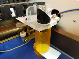
Objective Target Holder

If you do not have mirrors 1-2 aligned properly the beam will not enter mirror #3 at the correct angle and position. If the position & angle of the beam entering mirror #3 is not perfect the beam will not enter and exit the objective lens properly and likely will hit the side of any air assist cover that is on that assembly.
The hardest alignment task is to get the beam to reflect off mirror #3 and enter the objective lens perpendicular to the table and in the center of the writing heads optics.
Using the same theory of having multiple points on a graph I constructed another target holder that slides over the head.
This holder is made from a smaller medicine bottle (put size here) that has a slot cut in it just at the flange where the cap fit on.
A hole was drilled in the bottom of this bottle with a 24mm forstner bit and then filed slightly so it fits snugly over the objective lens cylinder. I am using a LO objective assembly.
The air assist nozzle is removed. A target is slid into the slot of the bottle and the modified bottle is pushed onto the cylinder until it seats at the top.
This provides a target that is closely on center to the objective lens.
When the beam is fired you can tell if it is in the center of the cylinder.

paper slot on the top of the medicine bottle

tube and target installed see dot burned during test

In position for a burn

Optical Targets and Measures

Using these tools and evaluating the targets will be in separate post. Here I will summarize their position using an optical layout where the positions of the targets are identified.

This photo is an initial attempt at describing the target placements and how to interpret the errors on them. Likely still confusing but as I complete the testing I will be back with more explanation. Note that this diagram is rotated 90 degrees, the machines bottom is on the right. No idea why I did that and this schematic need improvement.

Alignment Position #1

This photo shows the target in position #1 just as the beam exits the laser compartment. Zooming in on this photo you can see where the beam burned the graph paper and defines its position relative to the Z plate. The graph allows you to see its X (left-right) and Z (up and down) position as it hits the target.

Position #2

The target is moved to a position as close to mirror #2 as the holder will allow. Another burn is created either on the same target or a fresh one showing the position of the beam at this point along the gantry's path.
If the beam is moving;
  • parallel to the Y axis 
  • and on the same plane (Z) as mirror #1 

....then the burn at position one and position #2 should be in the exact same position on the target.


Position #3

The next photo shows where the beam hits the graphical target on the mirror. That graphic target is also cut so that you know where the mirror center is relative to the top edge of the mirror mount. As you can see the laser burned in the upper left quadrant just off center.

Position # 4

This position is just right of and as close as possible to mirror #2 but attached to the X gantry.
In this case the beam is in the lower right quadrant.

Position # 5

The target holder is then moved to the right extreme on the X gantry and a new spot is burned. 
The difference in position of the beam from position 4 will show the change in trajectory as it hits mirror 2 and traverses to mirror 3. 

Position #6

As the beam enters the last mirror (#3) it is folded downward and through the objective lens. This portion of the alignment is the most difficult because the #3 mirror aperture is small and the angle that the beam enters mirror #3 is critical. To make matters worse the stock #3 mirror mount has no adjustments.
There are 3 type of errors that can be found at this position:
  • The beam hits the mirror off angle, left/right or up/down 
  • The mirror is rotated off axis from the beams trajectory
  • The beam doesn't hit mirror #3 in the center
All of these errors have to corrected by adjustments to mirror # 2 and in some cases all the way back to mirror #1. To assist in seeing the trajectory of the beam and its position through the head the objective target holder is used.

Depending on how carefully this tube is constructed it give you a view of the beams placement concentric to the objective lens.

Summary

This method reveals the position of the laser beam at three points along its path showing its position in more that one axis at a time. This is expected to enable more accurate alignment, insureing that the beam is aligned to the gantry's planes of movement. 

Expected Advantages

  • Easy to see laser beam position in 3D
  • Easy to tell what direction to adjust what mirror
  • Target graphs create a record of aligned positions. Just date and keep them. When time to realign you can tell what has moved.
  • Use multiple targets at the same time to get a view of the entire path at one time with a single test pulse. I plan to build a version like this soon.

Next

Instructions on how to perform an alignment using these new tools.


Enjoy and comment,
Don


Improving the K40 Optics: Mirror #2 Replacement

K40 Mirror Mount and Adjustment Redesign: Part 2

DRAFT

This the 2cnd part is a continuation of my effort to redesign and improve the K40 optical path. 
Part 1 is here .....
In this post I will outline the design and assembly of a new mount for mirror #2. The same part design philosophy used in the first post was employed for mirror #2.

There are 4 posts that pertain to improving optical components and alignment:
Improving mirror #1
Improving mirror #2
K40 optical alignment tool theory & design
Using K40 alignment tools

Donate:

Please consider donating (button to the right of this post).
Your donations help fund additional research, tools and parts that I will return to the community as information.
For other information on the K40-S build use the  K40-S BUILD INDEX with schematics

Parts

  • Adjustable Lens Mount [Ebay]. This part seems to keep changing. If this link goes dead try searching for: "20MM/ 0.79'' REFLECTION MIRROR FIXTURE MOUNT FOR Co2 LASER MACHINE 1 PC Redsail"
  • 1/4" Acrylic [lowes]
  • 6- 4x.7mm flat head screws [Lowes]
  • 1- 4x.7mm pan head screw

Design

Similar to mirror #1's design this design consists of three parts: the base plate, sub-plate and rotary sub-plate.
Note in the pictures below my experimental alignment jig is installed. The peice of acrylic screwed to the gantry in the foreground is not part of the mirror mount. Neither is the cardboard flag and clamp to the right.


Installation

The #2 mirror assembly is assembled like the #1 mirror assy:
  • The rotating sub-plate is screwed to the bottom of the black mirror mount
  • That sub-assembly is then screwed to the sub-plate using one screw from the bottom
  • That sub-assembly is then screwed to the base-plate using two screws in the provided horizontal slots.
  • The entire assembly is then screwed to the gantry using the vertical slots shown just to the left of the belt and pulley
Note: I will add pictures of the part drawings to make this more clear.

Adjustments

The mirror has three coarse adjustments as viewed from the front of the machine:
  • Left-right using the two screws and slots to the left of the pulley.
  • Forward-back adjustments using the screws to the left and right of the rotating sub-plate.
  • Angular adjustments using the rotating sub-plate
Fine adjustments are made using the 3 brass screws on the black frame once the coarse adjustments are locked down.

Summary

A view of the cabinet showing the new optical assemblies in the homing position.


Next

I will install new mirrors and complete a full optical path alignment and report the results here.

Enjoy and comment,
Don


Sunday, November 11, 2018

Improving the K40 Optics: Mirror #1 replacement

K40 Mirror Mount and Adjustment Redesign: Part 1

DRAFT

Its has always been my plan to replace the mirrors in my K40. This past month my K40 has been acting up. It acted as if the HVT was gone and I was getting intermittent operation of the laser. I decided to replace the coolant and then troubleshoot the problem. In the process of clearing the bubbles out of the tube, by lifting and inverting it I managed to knock the #1 mirror out of alignment. Looking at the mounting and means for adjustment I decided it was far time I replaced the mirrors and their cheesy mounts with something better.

There are 4 posts that pertain to improving optical components and alignment:
Improving mirror #1
Improving mirror #2
K40 optical alignment tool theory & design
Using K40 alignment tools

Donate:

Please consider donating (button to the right of this post).
Your donations help fund additional research, tools and parts that I will return to the community as information.
For other information on the K40-S build use the  K40-S BUILD INDEX with schematics

Parts:

  • Adjustable Lens Mount [ebay]. This part seems to keep changing. If this link goes dead try searching for: "20MM/ 0.79'' REFLECTION MIRROR FIXTURE MOUNT FOR Co2 LASER MACHINE 1 PC Redsail"
  • 1/4" Acrylic [lowes]
  • 6- 4x.7mm flat head screws [Lowes]
  • 1- 4x.7mm pan head screw

Replacement Assemblies

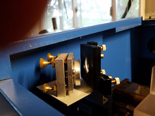
The photo below shows the mirror mount assemblies. On the right is the stock mount and on the left is the mount I bought from ebay.


eBay mount. Note much better adjustment screws and mirror securing ring. 


Design

Since the eBay mirror assy. is  larger than the stock unit a new mounting design was needed.
I decided to make a two axis mount since the entire assy. needed to be moved forward and back as well as positioned at 45 degrees to the exit of the laser. 
Four parts make up the new asy. From left, nut-plate, base-plate, sub-plate and rotary plate.


Base plate

To utilize the existing holes I designed a base plate and a nut plate. The stock designs base was bolted to the laser compartment using two screws and nuts. In this design the nuts were impossible to get to especially the rear nut. Instead I used two screws and fabricated a nut plate that could be held in place from inside the machine.

View from front of machine


Adjustable sub-plate

The sub-plate mounts on top of the base-plate. Slots allow it to slide perpendicular to the lasers output.
Note: I had to mill the surface of this plate slightly to get the beam in the middle of the mirror. The dimensions of this and the other parts will be added after testing is complete.


Mounting the mirror assy.

The mirror mount assy is screwed to the rotating plate from below with flat head tapered screws. The holes in the rotating plates are countersunk.


Rotating sub-plate

The rotating plate is mounted from below to the sub-plate and allowed to rotate. The mirror mount assy. is mounted onto this plate with tapered flat head screws allowing the mirrors to be positioned at 45 degrees to the lasers output. This screw hole is also countersunk. 

 Locking screw

A locking screw is added from the top side of the subplate to allow the rotating plate to be locked into position. 

Completed Mirror Sub-assy


Installation

The completed assy. is mounted on top of the base-plate. The mirror is coarsely adjusted by positioning it front to back and in a rotary fashion until the beam is in the center of the mirror and directed toward the #2 mirror (on the gantry). The sub-plate and rotary plate are locked down and ready for fine adjustments. The three adjustment screws on the mount are fine mirror position adjustments.

Fabrication

This unit was fabricated by hand but was designed to be fabricated using CNC machines.

Fusion 360 was used to create the design. Links to the design will be available if there are enough readers interested in building their own.

Laser Cut: 

All of the features of the parts should be able to be laser cut except the countersunk holes which are easily drilled using an appropriately sized centering drill.

CNC Router: 

The entire set of parts should be able to be milled by a cnc router.

Next

Mirror #2

The stock mirror # 2 will also be exchanged with a similar design as was employed for mirror #1 described by this post!

Laser Alignment Jig

For some time I have imagined a simpler way to align the K40 optics using a jig. Since I will have to realign the optics after I complete the installation of the new mirrors I plan to implement said jig. Stay tuned!

Alignment & Test

The entire optical path will undergo a realignment with the expectation that when finished my K40 optical path will be stable, robust and repeatable.

Enjoy and please comment,
Don

Sunday, September 30, 2018

Battling Electrical Noise in CNC builds

Practical Experiences with Eliminating Electrical Noise

I spend a lot of time in CNC forums helping fix the builder's electrical noise (eNoise) problems. These problems usually show their ugly head soon after a build is complete and the machine starts to be used in a variety of ways and under different loads.
This post attempts to capture my experience with this problem after heavily modifying a K40 and building an OX CNC.
At the risk of energizing the eNoise gods..... I have never had any noise problems with either of these machines!
I wondered why I have been so lucky when others inevitably get sucked into the intermittent hell of eNoise.

I suspect the answer lies in that I have always used a set of self-concocted design and practical implementation rules for minimizing eNoise. I plan to share them here. 

Before we start I will acknowledge that noise elimination is often a matter of art as much as design. 
Every engineer has a view and a favorite explanation of the best way to prevent eNoise. Most of these are correct given the right conditions. 
Often you will find a FIX but it will not make engineering sense. You will walk away in bewilderment puzzled that it worked but thankful that it did. Forever wondering why it worked!

The biggest source of eNoise in my experience is the lack of a grounding design. We tend to think of power and motor driver connections as high current low-frequency connections with stable voltages at low slew rates. However, every wire in modern CNC systems has the potential to carry high currents with voltage changes in the ns ranges. These spikes can travel in the ground system and create ground shifts that can drive digital electronics nuts! 
Good grounding design considers every wire in the system as a HIGH SPEED transmission line with the ability to shift ground levels, couple cross-talk and transmit signals like a radio transmitter.

Donate:

Please consider donating (button to the right of this post).
Your donations help fund additional research, tools, and parts that I will return to the community as information.
For other information on the K40-S build use the  K40-S BUILD INDEX with schematics

Sensors; not the Droids you're looking for!

The noise problem is not usually the switch/sensor itself... it's the sensor wiring, so the type of switch may or may not matter. I have had many builders tell me that optical end stops are noise prone and not to use them. I have used Optical sensors for decades in harsh environments without a problem. Most times when I thought the problem was the sensor it was actually a noise problem introduced by poor grounding.

Tug of war: Pull up or down?

I agree that in general pulling the input to the processor low is better than letting it be pulled high. I also know that the approach chosen depends on many other factors. The key is to choose the switch's pull-up resistor value such that enough the current is flowing in the wiring to keep any coupling from shifting that level. Long wires from end stop switches to processors are prone to be disrupted by nearby high current wiring. This is especially true when an end-stop wire is routed in a bundle with a 48VDC motor cable. That said, often the I/O cannot sink/source the needed current. I generally like to use low true for its fail-safe properties.

Seriously! It's the cabling design!

The most common problem is that sensing switches are connected through a long cable to the input of a processor that runs at 3.3v and it doesn't take much for a 48V @10 transient to create a 3v shift in the ground. Yes, many controllers have noise filters on the input but they often do not dampen the signal enough.
Noise generated from motors can easily shift an end-stop signal during a transient at a frequency the filter is not tuned for and can't damp. Since processors are capable of seeing very short transitions of a few volts it doesn't take much for a motor spike in a cable harness to be seen at the end of an end stop cables destination. It then gets interpreted by the controller as a real end-stop signal. These disruptions are hard to see unless you employ a high-speed differential scope!


Often or in addition, poor grounding design can allow for signal level shifts between the sensor and the receiver. Long wires have transient characteristics that act like antennas or dynamic resistances the shift a signal off of its resting value creating a false signal.

Optical isolators can be used between the sensor and the processor. That will allow the sensor signal to operate at a higher voltage (5V) and give isolation. However, the grounding on this board must also be properly designed.


Soapbox: I wish these controller board designers would build in optical isolation and higher voltage/current drive. Processor input/outputs are not designed to receive and drive lines directly and in highly static environments, the connected line can blow the inputs.

So the bottom line is that just pulling up or down inputs or changing sensor types is not sufficient for a noise-free system. Often these things work but it is more likely because these changes also happen to alter the characteristics of the signal, it's wiring, and grounding in a positive way.

I spend a lot of time over on the K40 Laser G+ with folks that have done conversions. The problem there is that the Laser Power Supply is +20,000 VDC @ +20ma which is a lot of energy. Conversions that are done without "designing" signal and ground circuits often have problems when the laser arcs, starts-up or changes current rapidly. Digital signals sharing wiring with High Voltage drive is a worse case environment.

The sensor type, cable type, routing, and termination all need to be "designed-in" for any hope of a noiseless system. Most folks view wiring and grounding as a static thing and focus more on the convenience of the builds wiring vs the dynamic nature of the signal paths at high frequencies.

Design Guidelines

Here is my design regime. Using this on my OX and K40 conversion has resulted in noise-free operation from the start. This seems like a lot of extra work but it pays off when you have a quiet system that behaves predictably. Signal and ground integrity is as much an art as an engineering discipline, your results may vary. 

Signal path design:

  1. Whether pulling the endpoint of a remote signal up or down, insure that the max amount of current is provided. You are trying to ensure that low signals cannot be pulled up by induced noise and high signal stay high in the presence of noise.
  2. Wire the signal using twisted pair (TP) from one end to the other. The ground is on one wire and the signal on the other. The ground lead of the TP should be grounded as close to the driver as possible at the source end and likewise at the receiver end. Sometimes it works better to ground only one end but that is usually in extreme cases and requires trial and error to know which end to ground. Cat 5 cables often have twisted pairs and make a nice signal bundle. You have to strip them back to tell if they are in a TP configuration. Do not run signals all together without TP in the same wire harness or bundle. I logically group my signals into CAT 5 cable groups of like signals based on my guess as to the driving circuits dv/dt characteristics. Its a lot more wire but it's worth it. A shielded cable can also be used but it can create as many problems as it solves. Where to ground the shield is often a mystery and requires trial and error. I have never had to use it because most noise problems I have encountered are conducted not radiated. 
  3. Route the input sensors wire/harness as far away from high current devices as possible. Definitely do not run motor signals in the same harness as sensors whether using TP or not. I run my motor wiring in a totally separate harness. The big offender here is the spindle [or HVPS]. Having signal wires even close to the spindle drive and /or its 48VDC power connection is asking for trouble. Consider that these wires (both the DC input and motor load) endure large and high current transients in the order of 10+ amps. In the case of my OX I mounted my spindle driver on the gantry within 6 inches of the motor. This allows the driver's output to be short. The only cable that travels through the drag chain is the 48V supply and that is a separate wire with the largest gauge I can afford.
  4. Keep the length of cables as short as possible, especially those cables between a driver and an inductive load like a motor.

Grounding Design:

  1. The ground system design must consider the path the current follows to get back to the source driver (that's usually the device on the PCB). Signals that are a long way away that are not grounded back to the source can experience ground shifts when exposed to strong transients due to line inductance, capacitive coupling, voltage drop, etc. The distance that the current has to travel can have a profound effect on the signal voltage seen at the receiving end of the wire. As an example, if a switch out on the gantry uses one signal wire but the return is tied to the frame out on the gantry, the return current has to flow through the frame back to the controller's ground connection then across the PCB and to the input receivers ground connection. Unless the frame of the gantry has a beefy wire running back to the controller the ground path may not exist at all or at best travel through moving ball bearings. In unknown paths like this who knows what voltage is dropped across what unexpected resistances/inductances.
  2. Power supply wiring should be designed just like signal wiring. Power supplies should be wired directly to their load. That means two beefy wires (power and ground) as short as possible directly to each load. The bigger the wire the better, size matters here. Do not run a PS's wiring to one load and then daisy chain the grounds to the others. Each supply has dedicated power and ground wires to the load.
  3. Ground each power supply back at the supply's terminal with an additional wire run to a common gas-tight connection on a common frame location. Yes, I mean a single lug that all PS ground lugs connect to. All supplies should literally have a beefy wire from the ground lug on the supply to the common frame lug. 
  4. Tie the safety ground from the AC plug to this same common lug. In weird conditions, I have found that isolating frame ground from PS ground to solve some noise problems. Try this only as a last resort.
  5. For the common ground, I use a bolt with soldered ring tongues stacked with star washers in between each lug. 
Admittedly this regime requires a lot of upfront signal and physical planning and uses a lot more wire and likely more drag chains than you hoped.
I have found it to be worth it.

Enjoy and comment
Don


Friday, September 14, 2018

Improved K40 Operating Panel

K40 Operating Panel

Donate:

Please consider donating (button to the right of this post).
Your donations help fund additional research, tools and parts that I will return to the community as information.
For other information on the K40-S build use the  K40-S BUILD INDEX with schematics

Background

For some time I have wanted to:
  • Have all the laser systems indicators to be in one place and up on the panel
  • Add a Laser tube surface temp sensor
  • Have a better looking power pot position meter.
  • Try out a sensor mounted on the head to detect a fire

Everything up on the panel

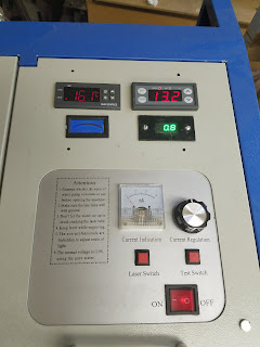
On the panel above:
Upper left: Senses heat at the head and shuts down LPS on overtemp with an alarm
Upper Right: Senses coolant temp and shuts down LPS on overemp with an alarm
Lower Left: Laser temp. Measures temp at the surface of the tube
Lower right: A DVM that measures the voltage on the LPS "IN" pin. 

I got all the sensing meters cut into the upper part of the panel. The Power setting meters bezel had to be hand fabricated. I am satisfied that they are all in one place but I wish I could have all the meters look the same. That's the result of some meters being discontinued and other not having controllers.


Cutting out the panel


The Plan

Nibbling Away

Final Cutout


Sensor Locations

The water sensor is located in the bucket at the end of the output pipe.

The laser jacket sensor is tie wrapped to the laser housing

The cabinet sensor is mounted on the head.
Note I have no idea if this sensor and the controller will respond fast enough to prevent a fire but I figure something is better than nothing at all.


Power Control Meter

More work needed to make this pretty!


Wiring

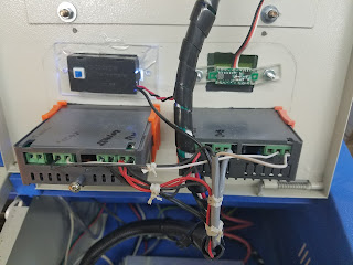
The meters that require the machine to be shut down have relays wired in series with the laser interlock circuit. These meters have high low setpoins and have audible alarms. 


Parts List

Upper left: Temp Controller
Lower Left: Thermometer
Lower right:  DVM


Enjoy & Comment
Don


Saturday, May 26, 2018

K40 Laser Power System Troubleshooting Guide

So Your Laser Won't Fire?

The laser power and control system in a K40 is a relatively complex and its the most unreliable subsystem of the overall K40. Therefore a lot of time is spent diagnosing and subsequently replacing and repairing parts of this subsystem.
It seems important that we capture what we have learned about troubleshooting and fixing K40's. 

Donate:

Please consider donating (button to the right of this post).
Your donations help fund additional research (like this one), tools and parts that I will return to the community as information.
For other information on the K40-S build use the  K40-S BUILD INDEX with schematics

Is it your laser power or the laser tube that is bad?

Good question! We don't have a definitive way of pointing to a bad tube but we can insure that the control system that drives it is working properly. Well almost. We can verify operation all the way to the input of the LPS but beyond that the HV characteristics of the laser tubes drive makes clear component identification dangerous, uncertain and expensive.
This guide helps eliminate everything up to and including the input of the LPS as the culprit. If everything is good to the LPS then I would:
  1. Replace the LPS 
    1. If you have certain symptoms you can try replacing the LPS's HVT. This is the most common type of LPS failure
      1. Repairing-k40-lps
  2. Replace the laser tube

The K40 Laser Power System Troubleshooting Guide

This guide provides K40 owners a flow chart for troubleshooting the Laser Power Control and Supply subsystem.

The Guide To Troubleshooting

The Elements of a K40 Laser Power Control Subsystem

  • Input power
    • AC plug and fuse
  • Control panel
    • Current control pot or digital controls
    • Laser enable sw
    • Laser fire Test button
    • AC power button
  • LPS
    • The high voltage supply
    • The laser enable loop
    • The local test PB
    • PWM input (L)
    • Local power control (IN)
  • PWM generator
    • The controller that converts gcode S commands to a PWM signal.
  • Laser
    • The laser tube that generates the optical power

Hints of Tube & LPS Failures

If after you check your laser power system with the troubleshooting guide and all is OK here are some additional hints:

Your tube might be bad if:

  • It does not light up at all
  • There is an arc from the anode to the frame. When the tube is bad it provides no load to the LPS. An unloaded (bad tube) LPS will often arch violently to the surrounding case
  • It has cracks
  • There is no current on the meter when the test switch is activated.

Your LPS might be bad if:

  • There is arching inside the supply
  • The mili-ammeter reads erratically at currents above 4ma
  • The current is lower at higher power settings than at lower power settings

Errors

If you find any kind of error or lack of clarity please make a suggested change in the comments.

Enjoy and comment,
Don

Thursday, May 17, 2018

Improved K40 Mirror Mounts Adjustments?

Alternate Mirror Mounts

Since I bought my K40 I have been looking for better mirror mounting and adjustments. I concluded that I needed to design a new version of the stock mounts.
Recently I found what seemed to be a compatible mount on ebay so this post documents and attempt to fit it into my K40.

Ebay Adjustable Mount

Will it Fit?

Below are some pictures of both mounts and an approximation of the differences in mirror center-lines between the two mounts if installed on the stock brackets.
The center-line of the Ebay mount is +.28
There isn't enough material to mill off the Ebay mount

Looks like the bracket can be lowered by approx. .28

Installation

I plan to replace the stock mirror mount bracket with a solid piece of aluminum [I never liked this cantilevered sheet-metal bracket] mounted solidly to the carriage.

Test 

TBD
I will fill this in after testing ......

Photos of the Ebay mount

The graduations on the paper are .25" (6.09mm).

Screw in retaining ring

Nice mirror restraint using nylon insert

For 20mm mirrors

Solid adjustments and tension screws


Enjoy and comment,
Don