INSTRUCTIONS:

Check out the new MoBeam posts! To find K40 conversion information use the "INDEX", "SEARCH" or "LABELS" sections in the sidebar.
Showing posts with label K40 Laser Tube. Show all posts

Monday, February 4, 2019

K40 Laser Power Control Characterization

Laser Power as a Function of Operator Controls

Recently +Ned Hill replaced his digital control panel with an analog one.
In the process he was thorough enough to take some measurements of the digital panels effect on laser power. Since Ned replaced the laser and the LPS this data may well describe an ideal K40 machine.
  • %PWM, 
  • Control Voltage (on the LPS-IN pin)
  • Laser Current 
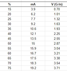
The +Ned Hill post and associated data are here and copied below for reference:

Tube%20power%20percent%20table 

This data shows the important relationship between the digital panels setting [%] and its relationship to the control voltage [V(G-IN)] on the LPS-IN pin and in turn the lasers power level. The LPS-IN signal results in the laser current seen at the ma meter [mA]. 

Observations About the Data

Multiple Linear Regression models can be constructed that more show us these relationships in mathematical form. Perhaps these simple math equations can help us predict the K40's performance and therefore more accurately choose settings.

I ran linear regressions on the above data to see if rational models could be derived to describe the laser powers behavior.

How Digital Panel Setting Control Laser Current Behavior

A regression was calculated using column 1 and 2 in the data above. The below equations represent a model of the relationship between panel settings and the resulting laser current.

equation 1: Tube Current = Digital Panel % * .2784 {R^2 = 0.996}**
equation 2: Digital Panel % = Tube Current/.2784

You can use these equations to estimate the laser current for a given digital panel setting or alternately estimate what panel settings will result in a what laser current.

The **R^2 value and this graph shows that the equations above should be pretty good predictors of laser current for a given panel setting. 

Note: the equation above predicts that at 100% Neds laser should draw approx 28ma of current.

How The Pot*** Setting Controls Laser Current Behavior

A regression was calculated using column 3 and 2 in the data above. The below equations represent a model of the relationship between panel settings and the resulting laser current.

equation 3: Tube Current = Control Voltage * 5.24 {R^2= .999]**
equation 4: Control Voltage = Tube Current/5.24

You can use these equations to estimate the laser current for a given pot setting or alternately estimate what pot settings will result in a what laser current.

The **R^2 value and this graph shows that the equations above should be pretty good predictors of laser current for a given panel setting. 

Note: The equation above predicts that Neds laser should draw 26.2 ma with the IN voltage at 5vdc.

*** the pot is sometimes called "Current Regulation" on stock machines that come with a pot.

How Do I Know What the Pot Setting Is?

Good question! The equation above uses "Control Voltage" as one of the variables so how do you know that value? Install a DVM on the POT. It tells you the control voltage it presents at the LPS-IN pin.

To use this schema read or set the pot until the DVM reads the voltage [control voltage] you calculated using equation 4 above. 

Your Mileage May Vary?

Statistical models are based on empirical data like that given in this post can be in error in a few ways, garbage-in-garbage out. 
+Ned Hills data is likely "IDEAL" since it was taken with a new tube and LPS. As such it should be a great reference as to what a K40 machine can do.

Here are some sources of error (assuming I did the math right):
  • Your LPS is weaker than Neds new one
  • Your Digital panel is defective 
  • The 5v supply used to drive the LPS-IN pin is an incorrect value
  • Your tube is weaker than Neds new one
  • Your mileage may vary

Local vs Programmatic Control

When firing the laser from the control panel the power is entirely controlled by the Digital Panel or Pot Settings. Therefore the equations above apply. 

However when under programmatic control from a PWM signal on the LPS-L pin the lasers power control is more complex. Its power is the product of the controller PWM % and the control voltage on the LPS-IN pin.

Using the Digital Panel To Set Laser Power

Laser current = (PgmPwr/100) * (DigitalPanel * .2784)

whereas: 
  • PgmPwr = the power setting in the control software as a percent
  • DigitalPanel = the setting on a K40 digital panel as a percent

Simple Example:

- DigitalPanel is set to 100%
- Lightburn power setting is 50%

     Laser current = (50/100) * (100*.2784)
     Laser Current = .5 * 27.8
     Laser Current = 13.9 ma

With the above settings when you push the test button you should see the meter read 27.8 ma
When running from program control you will run much less than 27.8 since the static value set by the digital panel will be reduced by any program setting less than 100%. 

Using The POT To Set Laser Power

Laser current = (PgmPwr/100) * (ControlVoltage* 5.24)

whereas: 
  • PgmPwr = the power setting in the control software as a percent
  • ControlVoltage = the voltage on the LPS-IN pin as set by the pot

Simple Example:

- Pot is fully on i.e. LPS-IN = 5vdc
- Lightburn power setting is 50%

     Laser current = (50/100) * (5*5.24)
     Laser Current = .5 * 26.2
     Laser Current = 13.1 ma

Is This Academic Knowledge?

If you expect your system to act exactly like +Ned Hill's then yes this may just be interesting information about Ned's machine. If however you value this information as a model of an ideal K40 machines laser power control behavior more value can be extracted. 

Ideas I have for using this knowledge are:

After taking a few settings *** on a machine you may;
  • See how close it performs to ideal
  • Create a model to match your actual machine by factoring the ideal model
  • Use the model to aid in choosing operational power settings
  • Attain a gauge to track your machines performance as it wears out
  • Troubleshoot laser control problems without electrocuting yourself  
*** take 3 measurements of laser current vs control voltage or digital panel settings.

Donate?

If this post helped you solve a problem, saved you time or was otherwise useful consider donating. Use the link in the upper right of the site.
Donations fund some of the expense of tools and materials for my shop and lab so I can bring you more content like this. 

Also let me know if there is other content you would like to see me explore!
_____

Thanks and please comment
Don

Saturday, February 24, 2018

Will a 40 Watt LPS Drive a 60W Laser?

Under-powering a Laser Tube

Caution: these are preliminary musings .....

Recently +Chuck Comito presented me with a question regarding how his 60W laser would perform with his stock 40W Laser Power Supply (LPS).
I hadn't spent much time looking at LPS specs matched against Laser Tube specs. I just assumed that if you got a bigger tube you had to get a bigger supply. 
Although to get to full power you will need a LPS that will output enough current to match the tubes specification, you can under power your laser ... theoretically. 

That said, +Chuck Comito is running a 60W K40 with a 40W LPS somewhat successfully, still testing. 

Donate:

Please consider donating (button to the right of this post).
Your donations help fund additional research, tools and parts that I will return to the community as information.
For other information on the K40-S build use the  K40-S BUILD INDEX with schematics

Why do we care?

Like most users when my tube goes bad I plan to upgrade to a higher power tube. We all know that our K40 really is a K30-35 in that these tubes don't actually output 40 watts.
30 watts is marginal for cutting thick materials and experience has shown us 50-60 watts is a better range for us makers.
The cost of upgrade would logically include the cost of a new tube and a higher wattage supply. This post suggests that you can upgrade your tube using your current K40 40 watt supply. That't a $100-150 cost savings and it allows us to use the stock supply to end of life.

The short theoretical analysis

1.) You can run your 60 watt laser with your 40 watt supply if you keep the current <=16MA
2.) Although at 16ma you will not reach 60 watts you will achieve a marked increase over what you had before at the same current.
3.) You can reach 60 watts if you run the supply at full capacity (22ma) but this will likely reduce its life.

My learning: you can upgrade your machine to 60 watts without getting a new supply unless you need run at the full 60 watts.

The long theoretical analysis...............

We know what the voltage vs current curve looks like, see the ref. at the bottom of this post.
I do not know what laser output vs current curve looks like when the tube is in the Normal Glow region [update: I added an attempt to model current vs optical power in the model below].
I assume that as long as the tube ionizes and the voltage is held at the operating voltage it will output light proportional to its current.

...We know that the needed trigger voltage relates to the length of the tube
...We know that the supply will current limit based on its pot setting up to close to 100% DF where is will be at max current.

Can you use a 40W supply to power a 60W laser?

This question of LPS wattage vs laser tube wattage is one I never did any research on. a I never compared the specs of supplies and laser tubes. So in the model below I captured some specs for comparison. I used similar supplies and tubes just different wattage's.
If you look at the specs for tubes and supplies in the model you will notice that the HV specs for a 60W tube can be met with a 40W supply! This means the supply will provide enough trigger to ionize and hold that ionization level.
There is a small mismatch between the current specs when using a 40w supply with a 60w tube. Note that the 40W supply must run at MAX current to provide enough current for the 60W tube, whereas the 60W supply provides enough current running below its max output i.e. its operating curent.

Assuming your tube and LPS have specs like those below, I would theorize that you can operate your 60W tube with a 40W LPS operating in the range <=16 ma and not >22.

The 40W LPS current will not likely get you to a full 60W. If things were linear, which they never are, you could estimate that with a safe LPS current of 16ma you will run 16/20 = 73% of rated power or 43.6W.

This may seem like a hugh loss of power but consider that your 40W was probably putting out 30W (as some high current). You now have a 13.6 watt (45%) increase over your previous setup. This means you have more power at a lower current. Not bad since you saved $100-200 in your 60W upgrade.

A Model

Using a purely specification based comparison of LPS's and laser tubes we can build a model to better understand how matching/mismatching LPS and laser tubes might perform.  Here is the analysis that led me to the conclusions I summarized above:


Enjoy;
Comments and corrections expected
Don

Wednesday, May 17, 2017

K40 Coolant Flow and Termperature Sensing

Background

Note: much of this approach has been replaced by: Improved k40 cooling circuit

The K40 laser needs coolant that is maintained at the correct temperature to prevent damage to the tube. It is not uncommon to forget to turn on a coolant pump or to have a pump or water system failure while running the K40. 
Sensors are easy to install in a converted K40 and the protection of the laser tuber certainly warrants the installation annoyance and cost of a flow sensor.

It is also desirable to know the temperature of the water and the tube. This post also outlines the installation of an inexpensive water temp sensor and control.

Donate

Please consider donating (button to the right of this post).
Your donations help fund additional research, tools and parts that I will return to the community as information.
For other information on the K40-S build use the  K40-S BUILD INDEX with schematics

Flow Sensor

Sensor

The loss of cooling water will certainly cause damage to the laser and the laser power system. Every system should have a flow sensor plumbed in series with the pump and the lasers cooling jacket.
The sensor that I use is:

This sensor needs to be installed on the output side of the laser. I made a hanger to hold it upright on the side of a 5 gal bucket. This way it insures that water is flowing out of the laser and it can detect any leaks from the pumps output to the sensors input.


Electrical connections;

The flow sensor is connected in series with the interlock circuit and in effect stops the laser from firing if there is no flow. 
See Build Schematics  for full machine details

If you for some reason do not want to add a sensor at least insure that the pump comes on with the machine. You can simply plug the pump and machine into the same power strip and turn them both on at the same time.

The End of My Tube Fell Off!

If you did not install a water sensor then at some point the pump will not be on, due to failure or  simply forgetting to turn it on, and the tube will overheat.

If the tube overheats the water jacket on the end of the tube can de-laminate and fall off.

Apparently if you are careful to keep it off the optical output area of the jacket you can use EPOXY it back on. I would surmise that high temp epoxy would be best.

GLUE IT BACK ON!

Temperature Monitoring

The laser must stay within its coolant operating range if it is to operate consistently and reliably. The cooler the laser is kept the more power it will be capable of. The power capacity of the laser will change with temperature therefore it is important to monitor the water temperature and prevent the laser from operating is the temp gets to high.
Install temperature monitoring electronics such as:

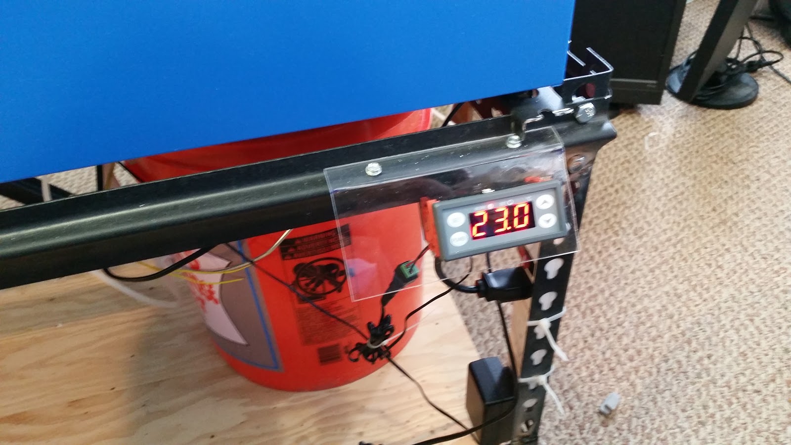
This device's relay contacts (NC) is also wired in series with the interlock circuit and will disable the laser from firing if the temperature is to high or low. The probe is put into the bucket near the output or the flow sensor.
See Build Schematics  for details.

This controller can be set up to produce an audible alarm outside of its set-points. (See the manual). I mounted it on thr front of the machine but plans are to move it up to the control panel later. The unit requires 12VDC so an additional supply is needed. Before I installed the 12V supply in my conversion I used a 12V brick plugged into a power strip. 


Enjoy and comment
Maker Don

K40 Coolant Pumps

Background

Information about common water pumps and coolant flow specifications

Donate:

Please consider donating (button to the right of this post).
Your donations help fund additional research, tools and parts that I will return to the community as information.
For other information on the K40-S build use the  K40-S BUILD INDEX with schematics

Water Pumps

From +Scott Marshall :"When all is well, the stock system should fill a 1 gallon jug about 1/2 full in 60 seconds. About 1/2 gpm or 2 Lpm. .................. the Little Giant PE-1 is a good quality replacement pump which is just right for the k40 and available worldwide."


Enjoy and comment
Maker Don

K40 Laser Tube Specifications, Maintenance, Failure & Replacement

Background

A collection of information about laser tubes and their care.

Warning: run your laser with properly treated distilled water as a coolant.

Donate:

Please consider donating (button to the right of this post).
Your donations help fund additional research, tools and parts that I will return to the community as information.
For other information on the K40-S build use the  K40-S BUILD INDEX with schematics

Laser tube operating conditions (Reci Laser):

  • Water cooling: using purified water; 2 to 5 liter/minute, (31GPH-80GPH)
  • Water temperature: 10-40℃, (50F - 104F)
  • The operating environment: temperature 2-40℃,(35.6F - 104F; humidity 10-60%.
  • The working current: test current is 29mA. The maximum working current is 29mA. The running current must be kept below 27mA. The life span can reach 8,000 hours if the current is kept below 25mA.
  • The ammeter must be connected to the negative electrode of the laser tube. When it is working under high current for the long term, the negative pole will appear light yellow and the life span will be shortened rapidly.
  • To protect dust from going into the insulation sheath, please wrap it with plastic film.

Laser Cooling and Condensation

Laser Tube Replacement

Tube Installation depends on the tube and there are multiple ways to connect to the pins on the tube. Pick your poison.

Basic Anode Connection Termination Methods

Unplug your laser from the mains power and let it sit for 1 hr.

Observe how the anode wire is connected to the tube including the wire routing and restraints.
Install the new anode wire in exactly the same way.

At the Anode end of the laser tube
  • Remove the silicone sheath from the anode connection. Minimize forces on the anode pin. It should pull off but if not you may have to cut it off.
  • Your anode wire may be twisted, screwed or soldered on the anode pin.
  • Remove or re-terminate the old anode wire. 
  • Replace the anode wire in the same way it was connected, twist, solder or screw.
    • If soldering, use minimal heat. Some recommend using Teflon tape to hold wires that are twisted see video below.
  • Route and restrain the wire in the same way. Usually, tie wraps around the tube moving away from the anode end toward the cathode end.
  • Flow silicon around the anode wire connection (use the white tube that came with your K40) 
  • Push the silicone tube over the wet silicon filling the tube. If you had to cut off the tube you will need to replace it with a piece of silicone tubing.
  • Add more silicon to the top of the silicon tube if needed
  • Let dry for 24hrs before using the machine
Alternate silicon: Permatex Blue RTV Gasket Maker. Available in auto and big box hardware stores.
703 adhesive silicone rubber insulation/potting/electronic waterproof sealant (the stuff that comes with the machine)

Other Methods

The videos below for removing a laser show connection and disconnection of the tube from its supply and can be used as a reference example:
  • Videos
  • Replacement Tidbits from the web:
    • "Disconnect power from unit!!
      Gently pull the existing silicone tube off the terminal post by gently twisting and pulling it along the wire itself.

      Use a soldering gun to heat the existing terminal post to gently release the existing wire connections. Then cut and clean up those wires. Also, clean out the silicone tube of the old residue. Of course, you need to remove the water connections and drain the tube. When installing the new tube keep the same orientation as the old tube and reconnect the water lines. Before attaching the power leads, screw down the retaining brackets and make sure the grounding wire is secured properly.

      Since you are replacing a tube, you already have a tube and terminal posts to practice on first. Make sure the wire leads are stripped at least 1/2" long, enough to be hand wrapped tightly around the protruding terminal post. The advantage of Rosin Core Solder is that it contains a built-in FLUX which helps to clean and bond.

      Before the wire strand is wrapped, make sure the silicone tube covering the wires is cleaned and placed back onto the wire. Once the wire strand is wrapped around the post, quickly heat and add some solder. Let it sit for a few seconds to cool and bond. The connection will be very secure. Just push the silicone tube back over the entire connection, completely fill the tube and connection with quick-drying silicone and in about 3 hours once the silicone drys, you are back in business."

Arching [needs content]

Reattaching the Water Jacket

Under shipping pressure or in the event the tube overheats the water jacket can become detached. 
Seems as if you can epoxy it back on! Check out this post.

Cleaning the laser tube water jacket

Replace all the water in reservoir with a couple of liters of vinegar and tap water... let it run for 12-24 hours replace all water with tap water only let it run for a bit... place outlet tube into a waste pan and flush adding a bit more tap water as your reservoir drains. Purge all water and replace with distilled water and some algaecide drops for aquariums. 
See: 

Laser Tube Specifications

Parallax: Laser Failure Modes and Warranty Info 


Enjoy and comment
Maker Don

Monday, March 6, 2017

Laser Response Charcteristics

Laser Response Characteristics

I moved the research that I have been doing into "laser response" to this post to capture it in a more focused way. 
Understanding the lasers response is an important part of getting to the best engraving control possible. The engraving control basics are described in Engraving-and-pwm-control.html. 
Understanding the relationship between the HV power (voltage and current), the tubes gas discharge characteristics and the lasing process of the C02 is integral to an understanding of how to optimize digital control of its power.

Donate:

Please consider donating (button to the right of this post).
Your donations help fund additional research, tools and parts that I will return to the community as information. For other information on the K40-S build use the  K40-S BUILD INDEX with schematics as a source of information 

Links to Related Posts

Electrical Modulation of a CO2 Laser

"Low frequency modulation can be achieved by pulsing or chopping the electrical power to the discharge. As the frequency is increased, the effect of the varying input decreases and above a few kHz, disappears entirely. The output of a DC or RF excited CO2 laser are both CW beams.
(From: David Toebaert (olx08152@online.be).)
This remark really holds for any kind of CO2 laser (the effect gets worse at higher pressure). It's just nature: it takes time for the molecules to 'meet' one another causing the delay. For a laser at 100 mbar (around 76 Torr) and a typical gas mix, the cut-off frequency is about 3 kHz. Above that the modulation of the input power is strongly damped and hardly visible anymore in the output power.

Simply think of the discharge as a *low pass filter for the input power, no matter how you excite the discharge. Of course, it's possible to modulate the input power at much higher frequencies (e.g. an RF supply can easily be modulated up to 100 kHz, that is, the Mhz signal is modulated at 100 kHz), but from the point of view of wanting to modulate output power, it makes no sense. Maybe it's beneficial for other reasons (e.g., discharge stability)."


*Whats a low pass filter?

The Effect of Modulation Cutoff Frequency 

The article above says that the laser cannot transfer input power changes that occur at a rate > than 3kHz. That means that the max time between changes that will be useful is: 3kHz  = 1/3000 = .00033 = 330 us. 
This means that in the model above the suggested pwm period (200us = 5kHz) is longer than the response time of the lasers gas ionization. 

If that is true then:
  1. The PWM period needs to be much longer or the gantry slowed down considerably
  2. The much faster times I measured (2us) by monitoring current suggests that it is not a  indication of the speed of light output. Is the current flow during ionization much faster than the light output?
More testing needed :(.


Laser Gas Discharge Characteristics

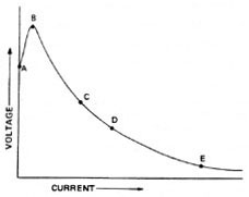
Negative Resistance
Negative resistance of a gas discharge: the voltage and current increase as described by ohms law until the discharge point. Then rapidly the voltage decreases and the current increases.

The hypothesis used in testing (above) and modelling; that the current flowing through the laser tube can be used as a faximile of the response of its light output does not track with the above modulation information :).

Laser Power Sources

Electric Discharge


Pumping the Laser


This video shows measurements of response speeds in the 4ms region.

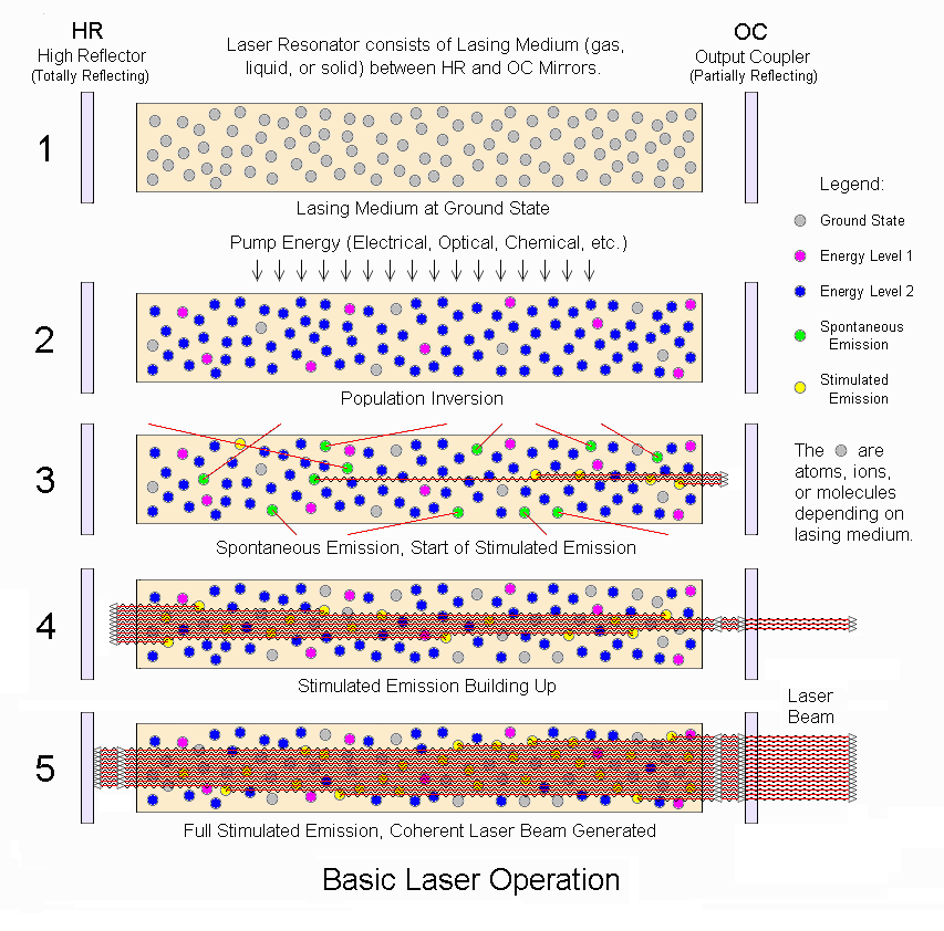
Laser Operation

Lots of info here: 

CO2 Info Summarized From Links

Gas mixture & its function:
13.5% N2 :    excited by gas discharge (pink glow) collides with and moves CO2 to level 3
9.5%   CO2: molecule that lases at energy level 3-2.
77%    He:    collides with CO2 at level 2 and then collides with tube walls for cooling
2%      H2:    gas discharge disassociates CO2 into CO and 02. H2 mixes with CO & O2 to regenerate CO2  

Ionization Voltage: 25 KV
Voltage at lasing:    13-15 KV
Negative resistance: 200-300K

Breakdown voltages

https://en.wikipedia.org/wiki/Dielectric_gas
https://en.wikipedia.org/wiki/Dielectric_strength

CO2: Air *.95
Air:  3,000,000 V meter

Laser Tubes

Synrad 40 W Lasers: Specifies a 100us rise time.

References To Aricles and Previous Work

https://en.wikipedia.org/wiki/Grayscale
Understanding CO2 lasers
Principles of plasma discharge
Dynamic PSpice Model of C02 Laser Tube
Gas Laser Electronics
Basic Laser Principles


-----------------
Enjoy and leave comments and discussion;

Maker Don

Thursday, July 14, 2016

K40 Coolant Conductivity Matters!

COOLING WATER "IT MATTERS"

After flailing for a few days with what I thought was a bad power supply or tube it dawned on me that I had never used distilled water (I am always tearing it apart and how conductive can the water be anyway?) and I knew that I had some algae in the tank.

I knew better from listening to others but seriously arching through the glass jacket through the water to ground in the tank? You better believe it, I have now proven it, to my satisfaction that is. I should have known better because I worked with someone that was blowing supplies every month and it turned out to be CAR antifreeze (that's definitely a no-no).

The symptoms was an intermittent screeching noise when the laser was in operation. It did not do it continuously and it did not do it every time. I thought it was coming from the LPS and finally was about to conclude that it was a failing winding inside the fly-back transformer. What bothered me was I could see no evidence of an arc even in a dark room. What I did notice was the flux beam shifting and changing shape at the anode end.

So I cleaned the system put in distilled water (3 Gal), powered it up and from then on no screeeeeeching just smooth wood smoking power. 

I wonder how many good supplies and tubes have been replaced or fry'd do to this problem.

Donate:

Please consider donating (button to the right of this post).

Your donations help fund additional research, tools and parts that I will return to the community as information and how-to's. 

The Simplest Cooling System Approach

"The simplest and safest for humans and machines it to use pure distilled water in a closed system which prevents contaminates that might encourage algae growth. Change water every 6 months with other maintenance." 

From +Arthur Wolf 

The underlying principle is that pure uncontaminated distilled water does not grow algae.

Coolant Conductivity Data

Here is some actual data for cooling water conductivity. I don't know why I never thought of measuring this before. I wish I had measured the water before emptying it.
------------------
I used a HM Digital COM 100.
The temp was about 60F-65F
----------------
Distilled water = 2.6 uS
Distilled/RV mix:6:1 = 142 uS
RV antifreeze = 414 uS
Don's tap = 370 uS Prestone (ethelene glycol) = 633 uS
Vinegar: 137 uS
"Purified" water: 10uS
Aquarium algaecide: See below

uS = micro-siemens

Algaecide for Algae Prevention

Algaecide: Tetra Algea Control
Active ingredients: 5% Poly [Oxyethylene (Dimethyliminio) Ethylene (Dimethylimino)
Ethylene (Dimethylimino) Ethylene Dichoride]
Recommended dose for Aquariums: 1ml per 12 gallons, 1 drop (.084ml) per 1 gal (3.8L)
Conductivity measurements: 1 drop added to 1 gallon of fresh distilled water.
  • Reading before algaecide control = 4.8uS
  • Reading after adding algaecide = 4.9 uS
Conclusions: this brand of algae-cide does not raise the conductivity of distilled water. (continuing tests to be conducted).
Expectations: adding 5 drops, (.42ml) per 5 gallon bucket of distilled water will not increase the conductivity of the water but will prevent algae growth.

Clorox for Algae Prevention

Clorox: mostly sodium hypochlorite

Sodium Hypochlorite Conductivity (note: these measurements were made with an ohmmeter and that will not work so do not use this data). A meter will not work to measure conductivity because DC polarizes the solution. AC is used to solve this problem so insure your meter or measurement method uses AC.

Here is a better method for calculating.  http://www.aqion.de/site/130

Estimating Practical use of chlorine:

How much Clorox needed to kill algae?

http://blog.enduraplas.com/water-storage-rain-harvesting/3-ways-to-eliminate-algae-growth-in-water-tanks

1/4 teaspoon per gallon of water = .042 oz/gal
.042 * 5 = .21 oz/5 gal = 6.2 ml/5 gallons

Measurements to attain conductivity at relevant concentrations:

  1. 2.5 gallons distilled water was added to bucket. Conductivity = 2.2 uS
  2. Added 3 ml Clorox. Conductivity = 44.9 uS
  3. Added additional 2.5 gallons. Conductivity = 22 uS
  4. Added 3 ml Clorox. Conductivity = 46 uS

Final (for now) formula:

Mix 6 ml of Chlorox with 5 gallons of water and expect the conductivity to be in the 40's uS.

Long Term Testing of Water Conductivity

I started a test of tap water conductivity to see what the conductivity does over time and as algea grows. I am also monitoring my main tank (B).

Test setup:
A. Water in bucket: from my tap sitting indoors in open container
B.  Water in my K40 tank

My K40 tank (B) has the formula from above.

Tracking my water conductivity over time

Water bubble treatment

Clearing bubbles after a water replacement makes water replacement a chore as I have to lift (quite high) and rotate the machine to clear them.
If I could find a way to clear the bubbles I would be more motivated to change the water more often.

Rotate the tube:

I can do this but it will require an optical realignment and it increases the chances for HV arc to the case as the anode swings closer to the cabinet.

Add Water Wetter

I tried adding "Water Wetter" @ 1oz per 3 gallons. It raised the water conductivity from 4.0 us to 410us making the coolant unacceptably conductive. The bad part is that it did not remove the bubbles much at all.
Water Wetter measured without dilution is very conductive and read infinity on my meter. Even after I rinsed a bottle that had the wetter in it and then added distilled water it raised the conductivity from 4.0us to 40us.
The bottle suggests 1oz per gallon so I was using only 1/3 the amount recommended for car cooling systems.

Add Dish Detergent

I added 1/4 oz of Dawn to 3 gallons after the test above. It did not change the conductivity and it did not stop the bubbles.

References

Water as a Coolant for Lasers
https://en.wikipedia.org/wiki/Purified_water

Enjoy and comment,
Maker Don