INSTRUCTIONS:

Check out the new MoBeam posts! To find K40 conversion information use the "INDEX", "SEARCH" or "LABELS" sections in the sidebar.
Showing posts sorted by date for query control+panel. Sort by relevance Show all posts

Tuesday, December 29, 2020

SKR to K40 integration

I recently worked with a K40 builder that needed to integrate the following:

This post shares the integration details.

WARNING: as of this date this integration has not been tested since I do not have an SKR board.

If you try this out and need help or got it to work please comment below.

Other similar work 

Connecting the SKR and the LPS;

I do not recommend the method used to attach the SKR to the LPS outlined in the  https://www.civade.com. The reasons are posted elsewhere in this blog.

The method that I recommend is outlined in this post. It uses one PWM signal from the smoothie to drive the LPS-L pin (or equivalent on other LPS). The LPS-L expects ground signal to turn on the laser, therefore an open-drain MOSFET is chosen as the output. 

laser-power-supply-control-take-2.html

If the SKR is truly a smoothie clone then this configuration should work.

About the SKR board

About the HY-T60 

Connection to SKR

This connection is for the typical K40 analog panel. Another configuration is needed if you have a digital panel. Comment if you need help with that.
The diagram below shows how to connect this type of supply including safety, test fire, interlocks, water protection, and power control pot.
On an SKR integration, the connection will be from SKR-E2 to the LPS-TL. This connects an open drain MOSFET on the SRK to the LPS-TL. When the PWM signal is true it will ground LPS-TL and turn the laser on.


SKR Equivalent circuit

This diagram shows the connection between the SRK's P2.4 pin 69, which is PWM capable, and one of the SRK's MOSFET drivers (Q1).
  • The output of this MOSFET is located at E1-2. 
  • Do not use E1-1 as it is VBB
  • Pick up the ground from DCIN-Gnd


Smoothie configuration

Below is my K40 configuration which uses a genuine smoothie boards P2.4 connection.
If the SRK is a true clone this configuration file should work.

Note: I have no way to test this as I do not have an SRK board.

Dons smoothie configuration

Note this is just the laser configuration section of the configuration file;

_______________________

## Laser module configuration
laser_module_enable                          true            # Whether to activate the laser module at all. All configuration is
                                                              # ignored if false.
laser_module_pin                             2.4             # this pin will be PWMed to control the laser. Only P2.0 - P2.5, P1.18, P1.20, P1.21, P1.23, P1.24, P1.26, P3.25, P3.26
                                                              # can be used since laser requires hardware PWM
laser_module_maximum_power                   .8             # this is the maximum duty cycle that will be applied to the laser
laser_module_minimum_power                   0.0             # This is a value just below the minimum duty cycle that keeps the laser
                                                              # active without actually burning.
laser_module_default_power                   0.3             # This is the default laser power that will be used for cuts if a power has not been specified.  The value is a scale between
                                                              # the maximum and minimum power levels specified above
laser_module_pwm_period                      20              # this sets the pwm frequency as the period in microseconds

switch.laserfire.enable true #

switch.laserfire.output_pin 2.5^ # connect to laser PSU fire (!^ if to active low, !v if to active high)

switch.laserfire.output_type digital #

switch.laserfire.input_on_command M3 # fire laser

switch.laserfire.input_off_command M5 # laser off

_________________________


Enjoy and please comment
Don

Monday, February 4, 2019

K40 Laser Power Control Characterization

Laser Power as a Function of Operator Controls

Recently +Ned Hill replaced his digital control panel with an analog one.
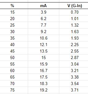
In the process he was thorough enough to take some measurements of the digital panels effect on laser power. Since Ned replaced the laser and the LPS this data may well describe an ideal K40 machine.
  • %PWM, 
  • Control Voltage (on the LPS-IN pin)
  • Laser Current 
The +Ned Hill post and associated data are here and copied below for reference:

Tube%20power%20percent%20table 

This data shows the important relationship between the digital panels setting [%] and its relationship to the control voltage [V(G-IN)] on the LPS-IN pin and in turn the lasers power level. The LPS-IN signal results in the laser current seen at the ma meter [mA]. 

Observations About the Data

Multiple Linear Regression models can be constructed that more show us these relationships in mathematical form. Perhaps these simple math equations can help us predict the K40's performance and therefore more accurately choose settings.

I ran linear regressions on the above data to see if rational models could be derived to describe the laser powers behavior.

How Digital Panel Setting Control Laser Current Behavior

A regression was calculated using column 1 and 2 in the data above. The below equations represent a model of the relationship between panel settings and the resulting laser current.

equation 1: Tube Current = Digital Panel % * .2784 {R^2 = 0.996}**
equation 2: Digital Panel % = Tube Current/.2784

You can use these equations to estimate the laser current for a given digital panel setting or alternately estimate what panel settings will result in a what laser current.

The **R^2 value and this graph shows that the equations above should be pretty good predictors of laser current for a given panel setting. 

Note: the equation above predicts that at 100% Neds laser should draw approx 28ma of current.

How The Pot*** Setting Controls Laser Current Behavior

A regression was calculated using column 3 and 2 in the data above. The below equations represent a model of the relationship between panel settings and the resulting laser current.

equation 3: Tube Current = Control Voltage * 5.24 {R^2= .999]**
equation 4: Control Voltage = Tube Current/5.24

You can use these equations to estimate the laser current for a given pot setting or alternately estimate what pot settings will result in a what laser current.

The **R^2 value and this graph shows that the equations above should be pretty good predictors of laser current for a given panel setting. 

Note: The equation above predicts that Neds laser should draw 26.2 ma with the IN voltage at 5vdc.

*** the pot is sometimes called "Current Regulation" on stock machines that come with a pot.

How Do I Know What the Pot Setting Is?

Good question! The equation above uses "Control Voltage" as one of the variables so how do you know that value? Install a DVM on the POT. It tells you the control voltage it presents at the LPS-IN pin.

To use this schema read or set the pot until the DVM reads the voltage [control voltage] you calculated using equation 4 above. 

Your Mileage May Vary?

Statistical models are based on empirical data like that given in this post can be in error in a few ways, garbage-in-garbage out. 
+Ned Hills data is likely "IDEAL" since it was taken with a new tube and LPS. As such it should be a great reference as to what a K40 machine can do.

Here are some sources of error (assuming I did the math right):
  • Your LPS is weaker than Neds new one
  • Your Digital panel is defective 
  • The 5v supply used to drive the LPS-IN pin is an incorrect value
  • Your tube is weaker than Neds new one
  • Your mileage may vary

Local vs Programmatic Control

When firing the laser from the control panel the power is entirely controlled by the Digital Panel or Pot Settings. Therefore the equations above apply. 

However when under programmatic control from a PWM signal on the LPS-L pin the lasers power control is more complex. Its power is the product of the controller PWM % and the control voltage on the LPS-IN pin.

Using the Digital Panel To Set Laser Power

Laser current = (PgmPwr/100) * (DigitalPanel * .2784)

whereas: 
  • PgmPwr = the power setting in the control software as a percent
  • DigitalPanel = the setting on a K40 digital panel as a percent

Simple Example:

- DigitalPanel is set to 100%
- Lightburn power setting is 50%

     Laser current = (50/100) * (100*.2784)
     Laser Current = .5 * 27.8
     Laser Current = 13.9 ma

With the above settings when you push the test button you should see the meter read 27.8 ma
When running from program control you will run much less than 27.8 since the static value set by the digital panel will be reduced by any program setting less than 100%. 

Using The POT To Set Laser Power

Laser current = (PgmPwr/100) * (ControlVoltage* 5.24)

whereas: 
  • PgmPwr = the power setting in the control software as a percent
  • ControlVoltage = the voltage on the LPS-IN pin as set by the pot

Simple Example:

- Pot is fully on i.e. LPS-IN = 5vdc
- Lightburn power setting is 50%

     Laser current = (50/100) * (5*5.24)
     Laser Current = .5 * 26.2
     Laser Current = 13.1 ma

Is This Academic Knowledge?

If you expect your system to act exactly like +Ned Hill's then yes this may just be interesting information about Ned's machine. If however you value this information as a model of an ideal K40 machines laser power control behavior more value can be extracted. 

Ideas I have for using this knowledge are:

After taking a few settings *** on a machine you may;
  • See how close it performs to ideal
  • Create a model to match your actual machine by factoring the ideal model
  • Use the model to aid in choosing operational power settings
  • Attain a gauge to track your machines performance as it wears out
  • Troubleshoot laser control problems without electrocuting yourself  
*** take 3 measurements of laser current vs control voltage or digital panel settings.

Donate?

If this post helped you solve a problem, saved you time or was otherwise useful consider donating. Use the link in the upper right of the site.
Donations fund some of the expense of tools and materials for my shop and lab so I can bring you more content like this. 

Also let me know if there is other content you would like to see me explore!
_____

Thanks and please comment
Don

Replacing the K40's Digital Panel with an Analog one

Why replace the panel?

It is not uncommon for the K40's digital panel to fail and more and more users are realizing the value of having a pot for control and an analog meter read laser current.

The digital panel

Understanding the k40 digital control panel

Adding an analog meter.

Adding-analog-milliamp-meter-to-k40.html

Converting the Digital Panel to Analog

Recently +Ned Hill had a LPS failure and tube replacement and decided to replace the digital panel and do a C3D upgrade.
We thought posting the conversion would be useful to others in the community

Schematic

I added a conversion diagram to the existing schematics I had for the digital panel.
It is located on the tab "Convrt 2 Analog".
https://www.digikey.com/schemeit/project/k40-powerled-v30-PM4QJBO303GG/


Conversion Instructions:

These conversion instructions are for supplies with all GREEN connectors. I can add the equivalent for other supplies upon request.

This conversion entails replacing the digital panel with an analog equivalent. The new analog panel has a switch, momentary push-button, pot, and digital voltmeter. The harness that goes from the LPS to the digital panel can be reused with the addition of two wires. These instructions refer back to the schematic.

-Build and mount the new analog panel (blue area)
-Remove the connector from the digital panel (orange area)
-Cut off the connector and strip back the wires
-Reconnect the 4x digital panel wires as shown in the schematic to the new panel (blue area)
-You will have to add 2x wires to the harness the G and the 5V

Note: this schematic also shows an installed pot and an associated control voltage DVM

Extracted from the schematic

Pictures From +Ned Hill Conversion

Supply Connections


Purchase Links

Please buy your parts using my affiliate links. It costs you nothing and it helps fund my activities. I defined a kit for this project which contains all the parts and links to amazon.
The entire kit is here and points you to these parts on Amazon.


Contributors

Thanks to +Ned Hill for his contribution to this post.

Donate?

If this post helped you solve a problem, saved you time or was otherwise useful consider donating using the link in the upper right of the site.
Donations fund some of the expense of tools and materials for my shop and lab so I can bring you more content.

----

Thanks, and please comment,
Don

Friday, September 14, 2018

Improved K40 Operating Panel

K40 Operating Panel

Donate:

Please consider donating (button to the right of this post).
Your donations help fund additional research, tools and parts that I will return to the community as information.
For other information on the K40-S build use the  K40-S BUILD INDEX with schematics

Background

For some time I have wanted to:
  • Have all the laser systems indicators to be in one place and up on the panel
  • Add a Laser tube surface temp sensor
  • Have a better looking power pot position meter.
  • Try out a sensor mounted on the head to detect a fire

Everything up on the panel

On the panel above:
Upper left: Senses heat at the head and shuts down LPS on overtemp with an alarm
Upper Right: Senses coolant temp and shuts down LPS on overemp with an alarm
Lower Left: Laser temp. Measures temp at the surface of the tube
Lower right: A DVM that measures the voltage on the LPS "IN" pin. 

I got all the sensing meters cut into the upper part of the panel. The Power setting meters bezel had to be hand fabricated. I am satisfied that they are all in one place but I wish I could have all the meters look the same. That's the result of some meters being discontinued and other not having controllers.


Cutting out the panel


The Plan

Nibbling Away

Final Cutout


Sensor Locations

The water sensor is located in the bucket at the end of the output pipe.

The laser jacket sensor is tie wrapped to the laser housing

The cabinet sensor is mounted on the head.
Note I have no idea if this sensor and the controller will respond fast enough to prevent a fire but I figure something is better than nothing at all.


Power Control Meter

More work needed to make this pretty!


Wiring

The meters that require the machine to be shut down have relays wired in series with the laser interlock circuit. These meters have high low setpoins and have audible alarms. 


Parts List

Upper left: Temp Controller
Lower Left: Thermometer
Lower right:  DVM


Enjoy & Comment
Don


Saturday, May 26, 2018

K40 Laser Power System Troubleshooting Guide

So Your Laser Won't Fire?

The laser power and control system in a K40 is a relatively complex and its the most unreliable subsystem of the overall K40. Therefore a lot of time is spent diagnosing and subsequently replacing and repairing parts of this subsystem.
It seems important that we capture what we have learned about troubleshooting and fixing K40's. 

Donate:

Please consider donating (button to the right of this post).
Your donations help fund additional research (like this one), tools and parts that I will return to the community as information.
For other information on the K40-S build use the  K40-S BUILD INDEX with schematics

Is it your laser power or the laser tube that is bad?

Good question! We don't have a definitive way of pointing to a bad tube but we can insure that the control system that drives it is working properly. Well almost. We can verify operation all the way to the input of the LPS but beyond that the HV characteristics of the laser tubes drive makes clear component identification dangerous, uncertain and expensive.
This guide helps eliminate everything up to and including the input of the LPS as the culprit. If everything is good to the LPS then I would:
  1. Replace the LPS 
    1. If you have certain symptoms you can try replacing the LPS's HVT. This is the most common type of LPS failure
      1. Repairing-k40-lps
  2. Replace the laser tube

The K40 Laser Power System Troubleshooting Guide

This guide provides K40 owners a flow chart for troubleshooting the Laser Power Control and Supply subsystem.

The Guide To Troubleshooting

The Elements of a K40 Laser Power Control Subsystem

  • Input power
    • AC plug and fuse
  • Control panel
    • Current control pot or digital controls
    • Laser enable sw
    • Laser fire Test button
    • AC power button
  • LPS
    • The high voltage supply
    • The laser enable loop
    • The local test PB
    • PWM input (L)
    • Local power control (IN)
  • PWM generator
    • The controller that converts gcode S commands to a PWM signal.
  • Laser
    • The laser tube that generates the optical power

Hints of Tube & LPS Failures

If after you check your laser power system with the troubleshooting guide and all is OK here are some additional hints:

Your tube might be bad if:

  • It does not light up at all
  • There is an arc from the anode to the frame. When the tube is bad it provides no load to the LPS. An unloaded (bad tube) LPS will often arch violently to the surrounding case
  • It has cracks
  • There is no current on the meter when the test switch is activated.

Your LPS might be bad if:

  • There is arching inside the supply
  • The mili-ammeter reads erratically at currents above 4ma
  • The current is lower at higher power settings than at lower power settings

Errors

If you find any kind of error or lack of clarity please make a suggested change in the comments.

Enjoy and comment,
Don

Monday, March 5, 2018

K40 Exhaust Air Sensor

How do you sense that your exhaust air is working?

My evacuation air system uses a pretty quiet blower and is controlled by a switch on my machine control panel. While working on the machine I noticed the blower was not working but had no way to tell for sure since other than the cabinet its a closed system. Opening the cabinet certainly worked but I wondered how hard it would be to build in a sensor. 
I have to admit this got out of control and one could easily argue that this problem did not need to be solved. But I cannot pass up a challenge to solve a problem that I have not yet solved.


Donate:

Please consider donating (button to the right of this post).
Your donations help fund additional research, tools and parts that I will return to the community as information.
For other information on the K40-S build use the  K40-S BUILD INDEX with schematics

The design

I started the design with the expectation that I could use a micro-switch with a flag on it like is used in furnaces. Turns out that it took much air to activate the switch and also blocked the airway. I also considered using a furnace air pressure switch but was not sure if had enough flow to activate this type switch. I will probably try one of these later although they are expensive.

After tinkering at the bench I decided to use an air vane, magnet and hall effect switch assy. to sense the air. The vane would sit in the air stream and an arm with a magnet activated a hall effect and amplifier that would in turn turn on an led. I powered the hall effect from a 120V to 5V switcher module I found on Amazon. 

Perhaps overkill but now I can tell if my exhaust air is on and it was a fun project. All other approaches were in excess of $100, this one cost me about $10 out of pocket.

The vane is a thin piece of acrylic with a block glued to the top edge. The activator arm runs through that block and is held in position with 2x set screws. The arm simply is inserted through two holes in the blowers body with pieces of plastic tubing keeping it centered during operation. The angle of the arm is adjusted so that when the vane is pushed by the air the magnet departs its position against the hall device. A piece of plastic tubing was pushed over the hall effect sensor to keep the magnet from impacting it when at rest.

I did not CAD the design as it built on-the-fly with parts I had in the bin however the photos and videos that follow I think make the actual build self explanatory.

PARTS

5V supply Note: this little modules are great for getting a small amount of 5V for sensors and such. They need a little attention as the outputs are not set up correctly. See the customer reviews for hints.


Brackets, actuator vane and actuator were hand made to fit.

Videos

https://photos.app.goo.gl/xsR4mNgfMi9G4oG32

Added a plug-able output because my K40 is now mobile


Enjoy,
Comments and corrections expected

Don


Monday, February 26, 2018

Understanding the K40 Digital Control Panel???

K40 PowerLED Control Panel

Newer versions of the K40 sometimes ship with a digital control panel. This panel retains the main power switch but the Calibrate (potentiometer), Laser Switch, and Laser test buttons are replaced by push buttons and a controller PCB.

Warning: this vintage K40 control panel does not ship with a laser current meter. Therefore it is not possible to know the actual operating power the laser is running at a particular digital setting. It is important to monitor the actual running power of the tube during operation to maximize the tube's life.
All tubes will eventually fail and are generally considered consumable but their life can be optimized. Tube life is proportional to the running current* so setting the machine to run at the minimum current required for the job and staying under the tube's rating will optimize its life.

Some users have made the argument that although running the laser at higher currents may shorten the life of the tube it also shortens job time, so it's worth it.

Add a Laser Current Meter

I recommend adding a current meter to your machine if you do not have one. The meter will assist you in running your laser at a current that is consistent with optimizing its life consistent with your expectations.

Add an analog meter to your K40

Most manufactures specify their tubes reliability @ 1500-2000 operating hrs running a working current of 20-22 ma. Check your tube's specifications, especially if you have replaced the stock tube.

The longest life I have seen specified is:


* There are other factors such as shelf life and operating temperature that cause a laser tube to fail. 

Donate:

Please consider donating (button to the right of this post).
Your donations help fund additional research, tools, and parts that I will return to the community as information.
For other information on the K40-S build use the  K40-S BUILD INDEX with schematics

Thanks to +Chris Hawkins for donating a panel for this exploration

Testing

A donated K40 PowerLED V3.0 was bench tested using a simple tester made from a USB adapter a few resistors, a voltmeter, and connectors. This tester provides 5V through a USB brick and listens to the IN and P pins of the panel.
This tester was connected to the panel and various tests were performed as described below.


Schematic

The schematic of the panel and the test board as it develops is here:


Interconnection with the Laser Power Supply (LPS)

You will note that this control panel connects both the P + & P- of the panel to the K+ signal on the LPS rather than the P signals on the LPS. Wow, now that's not confusing :(.

Also, note that nothing is connected to K- on the LPS and P+ & P- on the control panel are shorted together.

A LPS wired to a K40PowerLED Panel note the 4 white wires (from panel) and the black wires (from water sensor)

Operation:

The PowerLED [as best I can tell so far] utilizes an embedded processor to provide the functions of the panel. The main functions of the panel are to set the power level of the LPS, enable the laser to fire, and test fire the laser. The indicators and controls include:
  • Laser power display
  • Laser Switch
  • Laser Test Switch
  • Light Instruction
  • 3X +/-Digit Controls: 10, 1,.1

Laser Power Display

Indicates the % of the power the LPS is set to. This display indicates the % of the LPS max power it is set to via the IN signals voltage on the interface. This display is operational as long as the Laser Switch is enabled.
The LPS power is controlled via an analog value of 0-5V on the IN pin of the LPS.

Laser Switch

This alternate action PB enables and disables voltage to the IN signal and the Laser Power Display. When this switch is OFF the display is off (except for decimal points). When the display is off the IN pin to the LPS is reduced to zero volts. When this switch is ON the IN signal will be a voltage proportional to the % displayed on the Laser Power Display.

Laser Test Switch

When this PB is pushed the +P/-P signal is grounded for as long as the PB is held. The Laser Test Switch grounds the +P/-P irrespective of the state of the Laser Switch. When this PB is pushed the "Light Instruction" LED illuminates.

Digit Controls

There are 3 sets of digit controls with a + and - control for each. These pushbuttons (PB's) allows the setting of the respective digit in the Laser Power Display.

Testing Data

The following spreadsheet contains:
  • A table of the IN voltage vs the digital % power setting taken during the test
  • The calculated error between actual and calculated power values for % settings.
  • A math model (equation) for the input-output function of the panel

Model: 

VoltsOnLPSIN = 2.4562 * (%PanelSetting^2) + (7.6189 * %PanelSetting) - .2686

R^2 = 99.69% (good fit!)

Plotted Test Data & Error Calculations

5vdc Power Supply Loading

This panel draws about .2 amps from the stock K40 supply. That's about 20% of the safe 5vdc capacity. Note that some new machines have an LPS with the fan missing. I have to believe that the stock LPS is running on its limit (1 amp w/o fan) with these vintage machines.

NEW! Go figure, the IN output is a PWM signal

After being prompted to dynamically look at the IN pin of the panel by +Lukas Bachschwell who showed us a scope trace of the signal I was surprised to see that these panels acutely drive the IN pin of the LPS with a PWM signal!!! Thanks, +Lukas Bachschwell

PWM signal on IN


As you can see in my test setup the power was set to 50% and the IN voltage read 2.9. The readings here are average since the signal is actually a PWM square wave. My cheap DVM read 2.9 (which we now know is an average) 

"IN" Scope readings

Vavg: 2.98VDC. 
Duty: 58.8 [*seems like an 8.8% error from panel settings to actual?]
Freq: 24.55kHZ

*it would be useful to test and plot PWM linearity, i.e. panel settings vs actual PWM DF.

Why is the "IN" pin driven with a PWM? 

Keeping in mind that the digital panel wants 
  • Digital control of the power by switch settings
  • Power value display
Since most embedded controllers have PWM capable outputs it's rational to use PWM rather than a D/A approach. The controller can manage the display, switches, and the power this way.

Can we connect our controllers PWM output to "IN" on the LPS

Yes. An open-drain could drive the IN pin on the LPS but in my assessment, it does not gain you anything that I can fathom and has downsides.

Should we use the "IN" pin vs the "L" pin for power control?

No. Although this is an ok way to control power locally between the panel and the LPS, connecting a controller to the IN pin is a bad idea because:
  • We need manual control of the power for testing without a controller connected. 
  • We need a manual offset adjustment. This allows us to avoid having to make job setting* changes to account for laser depletion. The laser wears over time and uses so the power setting for any given job will change over time.
  • The IN pin is not optically isolated from the HV supply but the L pin is. Using the L pin is close to the same as driving the IN pin but it's optically isolated.
*the software that is sending GCODE

Using both the "IN" and "L" pins give us good local power control as well as isolated power control from an external controller. 

 Assessment:

The display and controls worked as expected. See the graph for data on accuracy and linearity errors.
I felt the .1 digit was a bit overkill for a Laser Engraver as I think there are many variables in the process that are much larger than a .1% laser power change. I did not plot the tenths.

The % settings vs actual output voltage were pretty linear. The error increased to its largest value (10.15%) exactly at 50%  and then decreased until it reached 100%. I suspect this is related to the type of D/A that the controller employs (actually it's likely because the IN signal is actually a PWM).
From a practical perspective, the linearity error doesn't really matter. What is important is whether the panel can provide a full range of adjustable power from 0-100%. In normal use the operator adjusts the power to suit a particular job noting the best setting and as the laser "wears" that setting will change anyway.

During testing, I noticed that sometimes the % value would decrease when the + key was pressed and sometimes it did not recognize a keypress. More of a nuisance when setting the power but a safety issue if the Laser Switch behaves that way.

Safety

My biggest concern is how the laser is enabled. The embedded controller apparently reads the Laser Switch (the fact it is a momentary PB yet operates as an alternate action switch is the giveaway) and sends the set voltage to the LPS.
If the Laser Switch is alternated to the OFF position it puts 0V on the IN pin and this is the only way the laser is "turned off". Essentially the laser is enabled, just at 0 power. I guess that is not theoretically different than disabling the power with one of the other enable functions (K or P) but it just feels wrong to me. It's reducing the power NOT disabling the LPS.

Let's consider how this safety mechanism can fail:
  1. A firmware bug does not turn off the IN voltage when the Laser Switch PB is alternated. Example: a bug turns off the display but leaves a voltage on "IN".
  2. The firmware does not recognize an alternate push of the Laser Switch and does not turn off the IN voltage. The operator does not notice the display is ON and thinks the Laser Switch was pushed. I have noticed during testing that sometimes the +/- keys and the Laser Test Switch does not work. The switch seems to be intermittent or the firmware is missing the press. 
  3. There is a failure on the control panel electronics that keeps the IN pin at a voltage.
  4. Somehow a voltage gets on the "IN" pin from somewhere else in the machine's circuitry there is no secondary means of inhibiting a beam.
  5. The display being ON or OFF is a confusing way to tell the operator the state of the "laser enabled" function. In most machines, the display turns on when the power turns on and stays on during operation. A specific indication that the laser is enabled is more appropriate. 
  6. Example dangerous scenario: the laser is enabled and the operator pushes the Laser Enable button, the display turns off but the IN voltage is left at whatever value it was before. The operator thinks the panel being off means the machine is powered off. During troubleshooting inside the covers, the operator starts a job ...... the laser is now active.
I doubt that this kind of circuit strategy for making a laser safe would be considered "fail-safe" according to OSHA regulations.


  1. Under the requirements of the ANSI Z 136 Standard, for embedded Class IIIB and Class IV lasers only, the interlocks are to be "fail-safe." This usually means that dual, redundant, electrical series-connected interlocks are associated with each removable panel.

Definition of a Fail-safe Interlock
An interlock where the failure of a single mechanical or electrical component of the interlock will cause the system to go into, or remain in, a safe mode.

Editorial Comments

Safety

I am not under any illusion that the K40 is SAFE as shipped although I do wonder what the FDA symbol on the K40PowerLED panel infers???? That said, I endeavor to follow OSHA and FDA recommendations whenever possible while doing conversions. This is to enhance my own safety and the safety of those mimicking my builds. To that end my machine has interlocks. These interlocks are not in series with any firmware and consist of nothing but wire, connectors, and mechanical switches. They all fail in the disabled mode...

For those using this panel; ensure that you install interlocks on all accessible covers using the P+ loop on the LPS. Put front and rear cover interlocks in series with the water-flow switch. 

Operation Improvement

The K40PowerLED panel would at first glance present itself as a high-tech implementation of K40 control. In my assessment, it does not provide much if any, advancement in the operation of the K40. In fact, the missing laser current meter makes an important operational measurement invisible to the user. Running overcurrent is the fasted way to shorten the life of a tube. Without a substantial improvement in functionality I am not willing to take the safety risk I think this panel may present.

The Good!

  • You can see a digital display of the % of max power the laser power is set to.

The BAD!

  • The buttons do not always respond or respond correctly
  • The panel draws an additional 20% of the already loaded 5V supply
  • No laser current meter leaves the operator blind to laser tube stress
  • Less linear than a linear pot 

The UGLY

  • Potential safety hazard in that the laser enables indication is confusing and the circuitry is not fail-safe.

Next steps

I do not think that further exploration into this panel will reveal more than the actual design that was used.
I am noodling if a safer, and more comprehensive control panel is wanted, needed, and cost-effective to improve the operability and safety of K40 conversions. Let me know your opinion in the comments..

Enjoy,
Comments and corrections expected;
Don


Thursday, February 1, 2018

Enhanced K40 Temperature Monitoring

Updated K40 Temperature Sensing

I have one point of temperature monitoring  in my K40, water. I recently moved my K40 to the garage shop and decided to get rid of all the hacks and partially complete conversions. Temperature monitoring was one of those on the agenda to be completed. Mostly the temperature controller needed to be remounted but while I was at it I decided to add some more gauges .....

Donate:

Please consider donating (button to the right of this post).
Your donations help fund additional research, tools and parts that I will return to the community as information.
For other information on the K40-S build use the  K40-S BUILD INDEX with schematics

More Temperature Monitoring

I already had a sensor in the water bucket connected to a controller that I had mounted lazily on the frame of the K40's kart.
This controller will alarm at an over temperature and since its relay is in the K40's interlock circuit it will shut off the laser.

This is the controller.  If its no longer available check for other similar ones. It needs to have an alarm function that opens the interlock when the temp setpoint it exceeded.


Gauge Mounting

The current controller/gauges were mounted on the upper part of the K40 control panel. It would have been nice if all these gauges were the same type. Then again their difference in appearance makes their varying purpose more obvious. In any case I went with function and cost over aesthetics.


One of my next projects will be to engrave acrylic labels for these. In the mean time their functions are:
  • Upper left: Cabinet temp
  • Upper right: Coolant temp
  • Lower left: Laser tube temp
  • Lower right: Laser power level

Gauge Installation

After removing the current control panel and then the hinged cover I used my nibbler to cut the holes for the new gauges. That nibbler is a must have "maker" tool!


Cabinet Temperature

This sensor is more of an experiment than anything. The sensor is located on the gantry near the air assist nozzle and is wired into the K40 interlock circuit. Its purpose it to sense a fire in the cabinet and turn the laser off. I have no way of testing or proving if this will work but I figured considering the damage a fire can do it was worth the effort and money! The idea is that a fire will melt the sensor and open the circuit. The controller will alarm if the sensor is disconnected and open the interlock circuit..... I hope.
I can imagine many cases where this may not work:
  • The head is not near the fire
  • The sensor shorts from the fire
  • The cabinet self destructs before the sensor sees it
I used this 2 stage controller which is overkill but can be used if I ever build in a water cooler. 
I plan to set this alarm on this sensor to the lowest practical operating temperature I can.


Laser Tube Temperature

A sensor was tie wrapped to the laser tube's glass and routed to the gauge. This sensor monitors only and is not wired into the K40 interlock circuit. I hope to learn more about the temperature in the lasers cabinet and eventually plan to add air to that cavity. This gauge required a spacer since the panel sheet metal was to thin for the mounting tabs to firmly hold the meter in place.


As an FYI you can see the new water sensor and air assist connections at the bottom of the photo.

Laser Power Meter

The last meter in this set is the digital voltmeter that is connected to the LPS's control pot. I had to add a frame and filter to the naked small digital voltmeter so that it had a better mounting, is more readable and somewhat nicer looking.
I added gel filter material between the display and the face plate to get the display to be more readable.

Old Power Setting Meter ... dangling

Mounting and Wiring

Meter mounting. Note the adapters on the upper meters.


Enjoy, comments and suggestions expected :)
Don