Cateleviered Design
The VG-L7X is mechanically a cantilevered design. The Y-axis is attached to the X carriage and has no support at the bottom (-Y) of its rail. I have doubts regarding how accurate this kind of design will perform.
Keep in mind the focus point for the Laser Diode is 3-10 mm from the head's lens. This does not leave much room for vertical positioning errors. I do not know what the DOF is for this laser but can imagine it is not much.
Stock Side Frames
The stock side frames are short acrylic sections that bolt to the ends of the X 20X40 Vslot rail. Seen in the foreground below, I could not imagine those short frames being stable enough to keep the head to surface dimension stable when the head is moved to its max Y dimension. Therefore I prototyped longer side frames using the dimension and hole placement of the short side frames.
New Side Frames
The new side frames fit well enough but after assembly, I noticed that the Y-axis was noticeably canted downward relative to the longer frames.
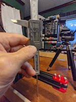
But the mounting error did not make up the for the full amount of error which measured approx. 3.97mm (.156)? This means that the laser is 4mm closer to the surface at its -Y extreme.
So I went looking for another source of movement?Sloppy Carriage
The source of most of the vertical error was pretty apparent when you lifted the end of the Y extrusion. The carriage wheels had lots of up-down play in the X axis extrusion.
You can see from the above video the Vslot wheels are not tightly cam'ed to the Vslot extrusion. There is NO adjustment to tighten the wheels up.
I think it is traditional to have eccentric columns on opposing wheels to make fine adjustments in these kinds of designs.
I do not know for sure if the cams above will fit but I will try them.
Improvement in Carriage Stability
I don't think the stock design is going to meet my marking quality/stability expectations.
In the current state the weight of the head "might" keep it from creating to much vertical error but the distance to the surface will still change from top to bottom of the vertical movement as the Y axis slants downward.
Cluegy Correction
- The downward error could be eliminated by adjusting the angle that the side frames mount to the X extrusion. Effectively lifting the Y-axis upward. The weight of the head would bias the wheels downward. This would not stop the carriage from bouncing upward under acceleration.
- The downward error could be eliminated by putting a rolling foot on the end of the Y extrusion. This foot would ride against an X cross member that would provide a fixed vertical reference. If the foot was adjusted such that the wheels were biased upward it may prevent any up-down movement.
Long Term Design Changes
I think the carriage wheels need tightening and the Y-axis needs support at its lower extreme. I am thinking that two things need addressing
- Eccentric adjustments of the X carriage wheels.
- A cross brace at the bottom of the travel allows the end of the Y-axis to ride on a fixed vertical plane. Not sure what is the best way to implement this.
Carriage Part Dimensions
Enjoy and please comment,
Don


Thank you For sharing a beneficial information.Also visit my article Fractional CO2 Laser Recovery
ReplyDelete