Reliable Cable Management
Sooner or later you have to create a reliable way to manage the LED cabling and air assist hose that connects to the movable gantry.This post outlines the use of a drag chain and the associated parts and build procedure.
This drag chain is purchased and installed horizontally from the K40 head bracket to the back right corner of the main compartment.
Two brackets are cut and bent to affix one end of the chain to the head and the other to the side wall of the main chamber.
For other information on the K40-S build use the K40-S BUILD INDEX with schematics
Donate:
Please consider donating (button to the right of this post).
Your donations help fund additional research, tools and parts that I will return to the community as information.
The Drag Chain Assembly
The bracket design(s) can be found in the Sketchup Warehouse.
Note there are multiple brackets in this file collection only two apply to this build.
I did not cut them on the K40 (it is being built) but I designed these parts to be laser cut.
The brackets are fabricated using .090 acrylic that I got from HD.
I bent these on my shop made acrylic bender but you can bend it in a vice with a heat gun.
Drag Chain
The drag chain I used came from amazon:Black Plastic Drag Chain Cable Carrier 10 x 15mm for CNC Router Mill.
Best I can tell the dimensions refer to the inner opening in the chain not the OD. However they are not precisely what I measured. Your results may vary. Different size chains are available but if you use other than this chain you will have to modify the brackets design.

Head Chain Bracket
This bracket mounts on the head using two of the base plates mounting screws.
The screw on the right and back are used, the left plates screw is exposed through a large hole in the bracket. This allows the bracket to be installed without removing or loosening all the base plate screws (just two) and thus messing up the alignment. My future plan is to print or cut a new base plate with all these features integrated.
To install the head chain bracket, insure the left front screw is tight then unscrew the right and back screw and add this bracket. Then add back and tighten the right and back screws through the head chain bracket.


Cabinet right side mounting bracket
This bracket is mounted to the drag chain and then to the main cabinets right side wall in the back right corner. The wiring and the air hose are routed from the electronics cabinet through the sidewall and into the drag chain.


 |
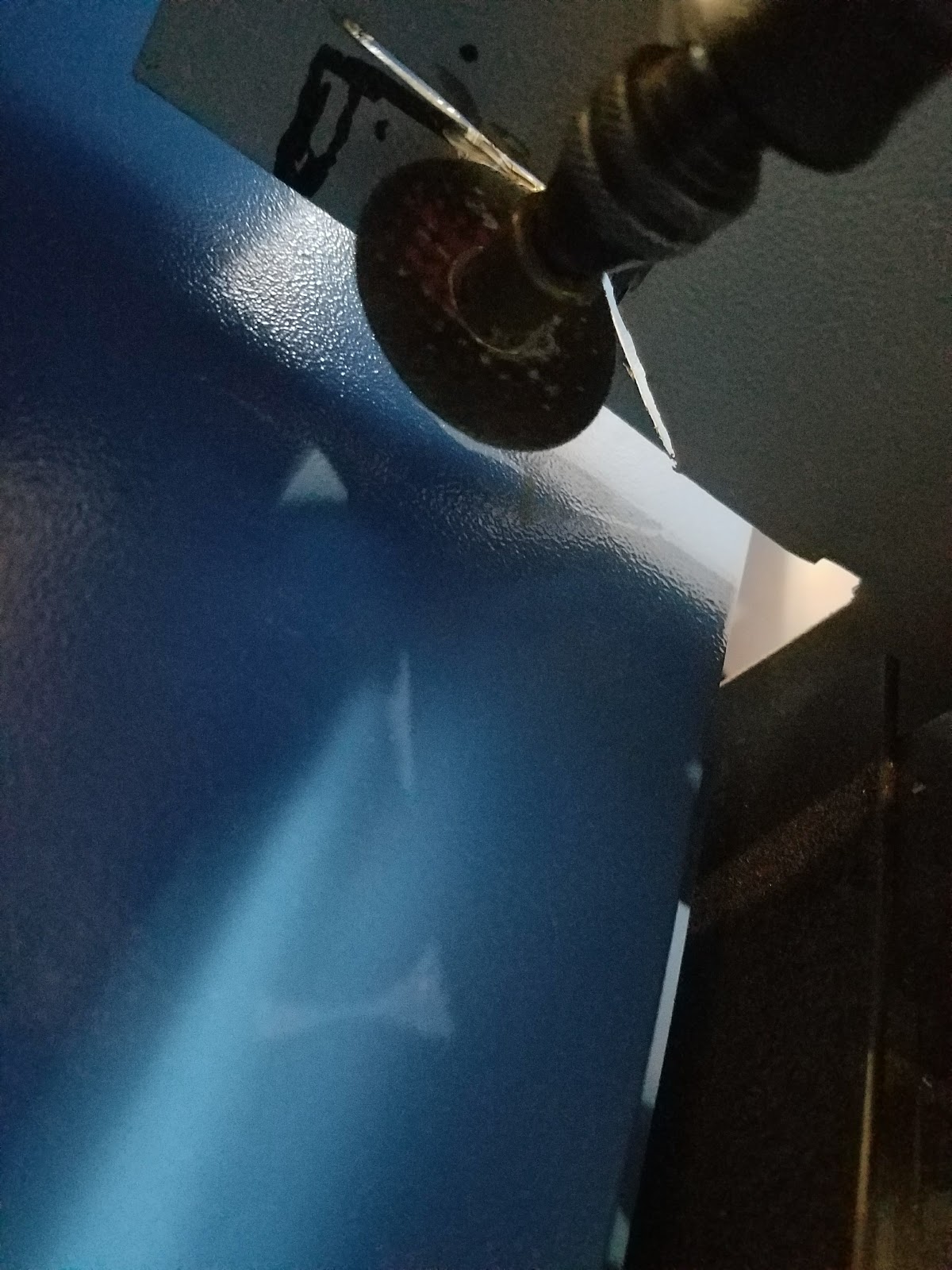
| Cutting the sidewall |
 |
| Mounted right side bracket |
 |
| Removed piece |
 |
| The right sidewall cutout |
Drilling the mounting holes in the side wall
Later there will be a template for drilling the holes in the side wall in the design file.
However you mount the chain to the sidewall, insure that the chain is mounted at the same level on the side wall as it is on the head. I moved the gantry into the back corner and traced the top of the drag chain on the wall. Then position the bracket mark the holes and drill. Hopefully the template will do this for you.
Cabinet Installation
The location and direction of the head bracket and the rear wall mounting is critical in getting the chain to clear all the optics as well as have smooth operation. The head bracket has fixed hole and mounts to the head plate so its easy to get in the right place but the rear bracket must be put in the right location manually.
Note: assembling the end links to the brackets can be annoying especially when you have big fingers like me. I used # 4 heat set inserts for plastic so that I did not have to hold a nut while bolting the bracket. You can install these using a soldering iron.
Note: assembling the end links to the brackets can be annoying especially when you have big fingers like me. I used # 4 heat set inserts for plastic so that I did not have to hold a nut while bolting the bracket. You can install these using a soldering iron.
In my setup I used 24 links not including the end mounting links. More links will create binding at the rear of the machine and it gets in the way of the beam when it is in the left rear of the cabinet..
The below pictures show the endpoint brackets in the 4 corner positions. Admittedly the head bracket can be optimized for strength and moved to the right to gain additional clearance away from the optical paths. The idea for the chain to be long enough to reach the corners but not so long that the arc of the chains wrap ends up in the 1st mirrors path when in the upper left or its trailing loop in the path of mirrors 2 - 3 when at the extreme right .
The distance from the back of the cabinet to the furthest forward mounting point on the head plate, when it is fully against the back wall, is about 73 mm and the width of a this drag chain when it is fully coiled back on itself is 68 mm. This means that when the drag chain is against the wall there is approximately 5 mm of gap between the chain and the wall. In practical application probably 1/2 that.
The distance from the back of the cabinet to the furthest forward mounting point on the head plate, when it is fully against the back wall, is about 73 mm and the width of a this drag chain when it is fully coiled back on itself is 68 mm. This means that when the drag chain is against the wall there is approximately 5 mm of gap between the chain and the wall. In practical application probably 1/2 that.
 |
| The chain must clear the optical path when rolled and at the extreme left rear position. |
 |
| Check upper right for clearance |
 |
| Back left showing clearance from laser beam |
 |
| Good at lower left, not to tight but not to long |
 |
| Lower right looks good. Probably could move the bracket right a bit. |
New Head Design
I completed a new head design and brackets that integrated this same drag chain.
Others approaches
I wondered why some mount the chain like mine (hinges vertical) vs rolling the chain horizontally across the x axis and vertically down the right side of the main bay (hinges horizontal). Like this design from +Ashley M. Kirchner.

The reported problem with running the chain with the hinges vertical vs horizontal is that the chain wears and sags and then can interfere with the gantry, sounds logical will see how these wear!
+Anthony Bolgar K40 has the same basic arraignment but winds the chain along the back wall from left to right. This clever approach eliminates any interference with the beam path. For some reason I could not get that method to work without binding, perhaps it is because my drag chain was bigger.
https://youtu.be/0r5sdS8zqY0
Other designs and parts
The operating drag chain
Note: the motion is jerky because I was manually jogging it.
+Ashley M. Kirchner design:
I like this design approach best but my goal was to have a K40 conversion whose parts can be laser cut so those without a 3D printer are set up. His bracket is in the SU design files linked above. I think this approach probably wears the chain better so it may last longer and it clearly is a setup that by design is out of the beam path.
Enjoy and leave comments if you have suggestions or questions.
Maker Don
Summary
Like most K40 conversions there is more than one way to solve the gantry cable management problem. I have used the above method because it was simplest for me to implement and met my minimal needs.+Ashley M. Kirchner design:
I like this design approach best but my goal was to have a K40 conversion whose parts can be laser cut so those without a 3D printer are set up. His bracket is in the SU design files linked above. I think this approach probably wears the chain better so it may last longer and it clearly is a setup that by design is out of the beam path.
To Do:
- Design a version of the +Ashley M. Kirchner setup that can be laser cut using a 7mm x 7 mm chain.
- Add drilling and cutting templates
- Design an integrated "laser cut" head plate that has all these features:
- Drag chain mount
- Laser finder mount
Enjoy and leave comments if you have suggestions or questions.
Maker Don
mazing work,your blog is realy nice.It is very easy to understand.
ReplyDeleteThank you for sharing with us this information.
SH Electronics Co. manufacturing Cable Drag Chain in pune,India.It has Variety of different product types with pre-defined cable carrier widths. Cable Drag Chain Manufacturer in Pune, Cable Drag Chain Manufacturer in India, Cable Drag Chain Supplier in Pune,cable Drag Chain Supplier in India.
Cable Drag Chain
Cable Drag Chain in Pune
Cable Drag Chain in India
Cable Drag Chain Manufacturer
Cable Drag Chain Manufacturer in Pune
Cable Drag Chain Manufacturer in India
Cable Drag Chain Supplier
Cable Drag Chain Supplier in Pune
Cable Drag Chain Supplier in India
Cable Tray is a hanging structure which is fabricated in different metals to fix all types of cables wiring/control cables in industry. It is the mechanical solution for hanging & laying the cables and provides protection against all environmental effects and technical contingencies.
ReplyDeleteHey good information, can you tell me where can i buy cable management online pls suggest me
ReplyDeleteNice blog
ReplyDeleteTelescopic Spiral Cover Manufacturers Chennai | Prashim Enterprises
Duct Hose Manufacturers in Chennai
Bellows Manufacturers in Chennai
Cable Drag Chain Manufacturers in Chennai
RK Industries is the leading brand of Top 10 Modular Electrical Switches Manufacturers in India. We are focused on the manufacturing, and delivering the first-class quality pipes. Our products are designed as the customer’s individual needs using top quality raw material and highly developed technologies to meet the industry quality standards. We also Provide Electric Switches, Wire and Cable , Submersible Cable at best price.
ReplyDeleteThank you for providing clear information a cable management. I have bookmarked this article for future reference.
ReplyDeleteTrailing Cables Manufacturers In India!
ReplyDeleteGreat blog! The detailed insights on HDPE Duct Spacers are truly helpful for cable installations. These spacers ensure proper alignment and reduce friction, extending the lifespan of cables. HDPE's durability and resistance to external factors make it an ideal choice. For quality products, check Duct spacer manufacturers in Ahmedabad!
ReplyDeleteNeon Cables India is Best Submersible Cable Manufacturers in India
ReplyDeleteleading manufacturer of high-quality cables and wires in India, offering durable and reliable solutions for automotive, house wiring, and industrial applications.
Great information shared here! We’ve been working in the cable management field for years, and quality always makes a difference. We are a bulk supplier and manufacturer of industrial-grade cable accessories — if you’re looking for reliable products, make sure to visit Anhui Shangbo Plastics for more details.
ReplyDelete