K40 Laser Power Supply (LPS) Control
During my journey to convert my K40 to Smoothie control I and many others have been frustrated trying to find a reliable, predictable and understandable means to digitally controlling the K40's laser power. For history see my previous post which I am superseding with this one.
http://donsthings.blogspot.com/2016/06/k40-s-laser-power-control-interface_86.html
http://donsthings.blogspot.com/2016/06/k40-s-laser-power-control-interface_86.html
CAUTION: LASERS AND THEIR HIGH VOLTAGE SUPPLIES ARE BOTH ELECTRICALLY LETHAL AND OPTICALLY DANGEROUS. THEY HAVE THE POTENTIAL TO KILL AND/OR BLIND YOU
STAY AWAY FROM THE HIGH VOLTAGE SUPPLY'S OUTPUT!
WEAR PROTECTIVE EYE WARE AT ALL TIMES WHEN OPERATING A K40!
DO NOT OPERATE A K40 WITHOUT THE PROPER LASER INHIBITING INTERLOCKS INSTALLED AND OPERATING PROPERLY!
BY READING THIS POST YOU AGREE TO USE THIS INFORMATION AT YOUR OWN RISK!
Donate:
Please consider donating (button to the right of this post).
Your donations help fund additional research, tools and parts that I will return to the community as information and how-to's.
Simple Smoothie PWM Control
A simple diagram showing how to connect to the LPS PWM from a smoothie 5x. You only need 2x wires.

NOTE ON CONFUSING LABELING:
In general, driver MOSFET's outputs on Smoothie compatible boards are labeled [+ or VBB] and [- or gnd].The +/VBB is connected internally on the board to a [+] power source it is not a signal.
The [-/gnd] is connected to the DRAIN of the MOSFET (not ground).
For open drain connections you want to be connected to what may be marked [-/gnd] pin. Pick up an actual ground for that signals cable from another pin (like the picture above).

You can remove the pot and install the red jumper which allows the PWM to have full control. I do not recommend this configuration. Although you will have full software control of power you will have to regularly calibrate your machine for max power. See Setting " Power Calibration"
Leave the Pot in
I recommend this approach!You can elect to keep the "Current Regulation" pot installed in its stock configuration. If you do the actual laser power will be the product of the pot setting AND the PWM setting.
I.E. if the pot is set for 50% power and the PWM is asking for 50% power then the actual power will be:
Actual Power = Current Calibration % * PWM duty cyle
Example: Pot set a 50% and LaserWeb asking for .25%
Power = .5 *.25 = .125 or 12.5%
If you leave the pot in you can allow the software to control the power within its min - max range (0-100%) that the pot is set to. The Pot becomes an overall intensity control and you do not have to calibrate the machine for MAX power.
See this developing post for more detail regarding the PWM configuration effect on engraving:
http://donsthings.blogspot.com/2016/12/engraving-and-pwm-control.html
 |
| Actual photo of how my machine is wired |
Power calibration
I do NOT recommend taking the "Current Regulation" POT out.
Its my expectation that you remove the pot and pull the IN to 5vdc or set the "Current Regulation" (IN) to full on you will need to calibrate the power settings in your K40-S to keep the power range below the 18ma max operating range.
Its my expectation that you remove the pot and pull the IN to 5vdc or set the "Current Regulation" (IN) to full on you will need to calibrate the power settings in your K40-S to keep the power range below the 18ma max operating range.
Power settings and verification
I have not completed the testing on this process but figured those looking for precision control of power would value having a preview. This is less important when cutting than when engraving or carving.
I recommend running a grey scale test and if that images but does not look good I would suggest something is wrong with your settings not your connection to "L".
When using the L line for normal operation with a pot installed you should have it set to a position that limits the current to 18ma and let the controller vary the power within that range. If you have the pot removed and the IN line jumper-ed to 5VDC you have to insure that the driving software never exceedes the max 18ma current level.
Setting the max power
If you are set up right the controller will not exceed the limits set in the configuration and you will not exceed where you want the tube to operate i.e less than 18 ma.
To calibrate:
- Verify your max power by using the test button to find out what the max current is with the pot full on. Example: your current meter at max pot setting = 24ma
- Then calculate what % you want the max limit of be and set that in the configuration file. Example: 18/24 = .75. You want the max power that the controller ever asks for to be less than 75%.
I advise testing by sending G codes for various power levels and verifying that it stays within limits on the current meter ("Current Regulation Pot"). Make sure the Gcode keeps the laser on long enough to get a good reading on the analog meter.
[later I will post a test for this]
[later I will post a test for this]
After this is set up the controller should have full control of the power while keeping the power below the 18ma limit.
You may need to re-calibrate as your laser wears and power levels drop.
Note: this approach to Max power setting may reduce your software's dynamic range for engraving. That is why I do not recommend setting the max power this way.
See: http://donsthings.blogspot.com/2016/12/engraving-and-pwm-control.html for further development and research.
-----------------------
The remaining sections provide design and engineering information
Thanks for help from these folks .....
Thanks to +Paul de Groot and +Kim Stroman for providing a schematic and broken power supply, respectively, as a source of information.
Multiple versions of LPS
We now know that this confusing situation is exacerbated by the existence of multiple versions of LPS's that are in use. Many look the same externally but are different internally.
You cannot tell what type of supply you have by any external means ... that I have found.
Below are pictures of three few supplies. We have a schematic of Pauls and Kims. Mine I can only poke from outside because it is in service.
Caution: I know there are other versions of LPS out there and this analysis applies to the ones shown in this post. I will add the others as I get samples to trace.
Donate your dead LPS to research
If you have a dead one that you want to donate to this research email me at:don_kleinschnitz@hotmail.com
PS designation
For this post I am creating a designation for these supplies. To date I have found 3 types and I designated them like this:
- First letter: the color of the AC power connector
- Second letter: the color of the control connector
- Third letterL the color of the DC power connector
- Third letter: the color of the Power-on LED
Green-Green connectors with Red power LED
Designated G-G-G-R in this post
 |
| +Paul de Groot's supply |
Green-Green with Green power LED
Designated G-G-G-G
 |
| +Kim Stroman's supply. Note: flyback disconnected |
Green-White connectors with Green power LED
Designated G-W-W-G
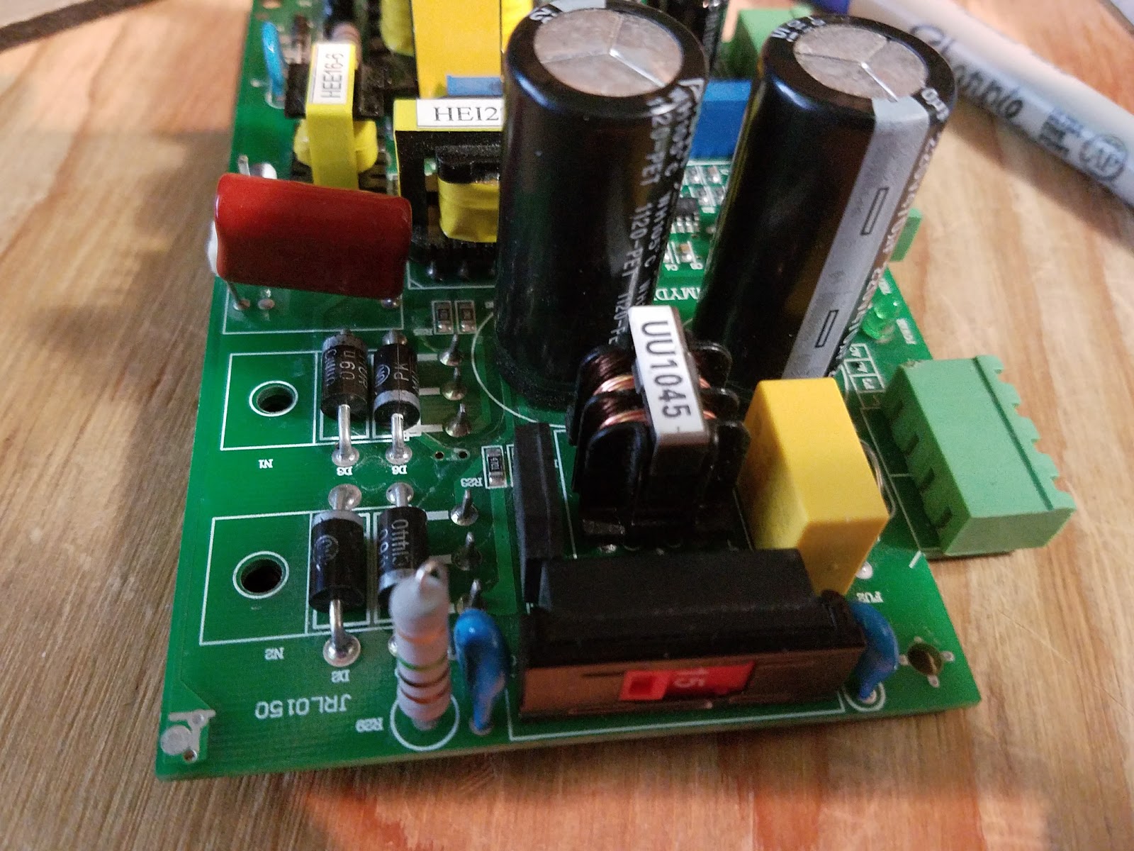
 |
| My K40 LPS |
More LPS style and interconnect references
Schematics:
For G-W-W-G style supply:
LPS schematic PDFLPS schematic download (.sch)
For GGGG style:
A share-able schematic that is a work in progress...
PWM circuit sketch not in main schematic yet
 |
| PWM circuit |
For the G-G-G style supply here are some simplified schematics of the input controls:


Note that for HV isolation the "ENABLE" and "L" inputs to the LPS are routed through opto-coupler's. The external control signal simply provides a ground to the cathode of the opto-couplers transmitting LED to operate.
In the case of Smoothies open drain control (see PWM Control Via L, below) the opto-couplers LED is connected to the FET's drain and when the FET switches on current flows in the led illuminating it, correspondingly turning on the receiver transistor.

LPS control theory of operation
Although we are not yet finished understanding how external controls are implemented internally on all LPS versions we suspect that from an external perspective the fundamental behavior of these controls are the same.
In general the LPS is switched mode AC-DC supply that controls current with Pulse Width Modulation that drives a flyback arrangement and voltage multiplier. This supply creates a regulated and very high voltage.
AS I NOTED ABOVE: THESE SUPPLIES OUTPUT LETHAL VOLTAGES.
So as to minimize confusion; in a K40 conversion there are two PWM functions at play. The one that is asserted by the digital controller (like a smoothie) and the another that is employed inside the LPS using a PWM IC. These LPS's are designed to operate both stand alone and with a remote means of controlling the level of power.
IMO: When a digital controller is providing PWM control the internal PWM is redundant.
Basic control function behavior
There are three fundamental control functions on these supplies that are sometimes referred to by different names. I will give them a generic name for this post and also associate them with their real names where I can.
ENABLE:
Note 2: You will notice that this configuration of FIRE is exactly the same as #1 Enable behavior above. In some supplies it seems that there is an AND function of Enable and FIRE that controls the output of the PWM generator. [more verification needed here].
At least two ways have been found for how this control is accomplished.
The challenge with defining the RIGHT and WRONG way to configure PWM control of a K40 LPS is that you can make multiple approaches work. The fact that there are multiple unrecognizable versions of these supplies does not help matters.


ENABLE:
The "ENABLE" signal controls the internal PWM controllers output. If Enable is not asserted the laser will not fire because the internal PWM's Duty Factor (DF) is either 0 or in alternative implementations its output is disabled.
- Ports that behave this way are: TH,TL, K.
At least two ways have been found for how this control is accomplished.
- Enable is connected through an opto-coupler that when asserted* enables the output of the internal PWM generator. If enable is not asserted the PWM generator is disabled.
- Enable is connected to an opto-coupler who's output transistor is connected to a differential amplifier. When enable is NOT asserted* it biases one leg of the amplifier insuring that the IN voltage will not generate a PWM DF > 0. If enable is asserted* the PWM DF will proportionally follow the IN voltage.
FIRE:
The FIRE signal enables the output of the internal PWM to run if asserted and remain off if not.- Ports that behave this way are: L and Enable #1 above.
- Connected through an opto-coupler that when asserted* enables the output of the internal PWM generator. If FIRE is not asserted* the PWM generators output is disabled.
Note 2: You will notice that this configuration of FIRE is exactly the same as #1 Enable behavior above. In some supplies it seems that there is an AND function of Enable and FIRE that controls the output of the PWM generator. [more verification needed here].
Power Control (PC)
The PC signal is the means by which the LPS power can be controlled with an analog signal. This signal can be in the form of a variable voltage from a pot or an analog voltage from a remote controller.
To add to the confusion PC can be overloaded by a digital signal of the right voltage making the IN a power ON-OFF function. More on this further down.
IMO: this control was not intended to be a digitally controlled input. That is in spite of the fact you will find many configurations and vendors that promote using it as PWM control.
- Ports that behave this way: IN
- The IN signal adjusts the current through an opto-couplers input LED whose receiver provides a corresponding and proportional voltage to the PWM generators DF control. This IN signal is isolated and connected to the cathode of the coupler's input diode. In this configuration the IN signal expects a resistance to ground that changes the current in the opto-couplers LED transmitter and correspondingly changes the current in the output transistor. Its note-able that the opto-couplers used in this analog mode and the ones used in a digital mode* are the same component part. The only operational difference is how the current through the diode is provided.
- The IN signal is directly connected to one leg of the internal PWM controllers differential amplifier. When enable is asserted this amplifiers output follows the IN signal adjusting the internal PWM's DF and in turn the output power. When enable is not asserted the other leg of the amplifier is at large enough voltage to prevent the amplifier from outputting a voltage proportional to IN effectively creating a PWM DF of 0. In this configuration the IN signal is not opto-isolated from the supply.
Putting LPS PWM control into practice on a K40 conversion
The current investigation and its corresponding espoused theory provide a basis for effectively using PWM control in a K40 conversion irrespective of a specific supply's actual internal operation.The challenge with defining the RIGHT and WRONG way to configure PWM control of a K40 LPS is that you can make multiple approaches work. The fact that there are multiple unrecognizable versions of these supplies does not help matters.
Therefore to start with I am going to define how I plan to use the information provided above. Then when I complete building and testing it I will update this post. Other configurations than the one outlined below may work. Its my judgement that the one below is the simplest and most reliable.
Interlock control:
Leave the stock wiring for the "Laser Switch" and insert in series with this circuit any additional interlocking functions including cover switches and temperature monitors.
PWM control via 'L":
Connect the controllers PWM function through an open drain (OD) or open collector (OC) to the L pin. Choose a transistor that is connected the controllers PWM function. Insure that in your controller you configure the input to this transistor to assert in such a way that the transistor provides a ground. In other words, when PWM from the processor is TRUE the transistor should be turned on. This transistor is connected to the L pin without any form of pull-up or level shift-er. This pin from the controller will be isolated from the LPS.
In the supplies we tested this signal can be found on the rightmost pin in the LPS DC connector.
IN:
In the supplies we tested this signal can be found on the rightmost pin in the LPS DC connector.
 |
| A typical Open Drain configuration |
 |
| The equivalent circuit of the K40-S PWM connection |
Since we are providing digital power control to the LPS through "L" we do not need another form of power adjustment for PWM control but we do for max power setting.
As the laser wears the current required to get the same power changes so the power ranges changes .
As the laser wears the current required to get the same power changes so the power ranges changes .
Certainly we can change the max-min ranges in smoothies config file but why go through that annoyance.
Leave the pot in and it functions as an intensity control (see Power Settings and Verification above)
Leave the pot in and it functions as an intensity control (see Power Settings and Verification above)
However recognize that the controlled power is the product of the pot setting and the Smoothie PEM setting.
Therefore if the controller is set at 50% and the pot is set at 50% the actual power may be (.5*.5) or .25%. This is because the controller is turning ON the LPS whose power is fixed at 1/2, 1/2 the time .... is that sufficiently confusing :).
More detail at these posts:
http://donsthings.blogspot.com/2016/12/engraving-and-pwm-control.html
More detail at these posts:
http://donsthings.blogspot.com/2016/12/engraving-and-pwm-control.html
Level shift-er use:
It has become common practice to use a level shift-er connected between a 3.3vdc PWM controller signal and either the IN or L signal on the LPS.
I believe that this configuration can be made to work but creates a level of complexity that is unnecessary. Most controllers have Open Drain or Open Collector drivers available. These are less complex to configure and wire and use less parts.
To test this setup. Before you connect to the LPS leave R4 in and connect this circuit to the controller and look at Q2 collector with a scope. Insure that the collector of Q2 is being pulled to ground with the assertion of a PWM pulse.
I do not plan to test this configuration.
A 0-5vdc PWM signal can be connected to the IN pin without a pot and operate properly. I don't see the value in using this approach as the configuration I recommend gives you the option to keep or discard the pot while providing opto-isolation. This configuration will also require constant max power calibration and configuration settings changes.
I believe that this configuration can be made to work but creates a level of complexity that is unnecessary. Most controllers have Open Drain or Open Collector drivers available. These are less complex to configure and wire and use less parts.
When an OC/OD is not available:
If there are no OD/OC outputs available I would use a discrete circuit that connects to a processors 3.3vdc signal to (R3) and connect "L" to the collector of Q2. Remove R4.To test this setup. Before you connect to the LPS leave R4 in and connect this circuit to the controller and look at Q2 collector with a scope. Insure that the collector of Q2 is being pulled to ground with the assertion of a PWM pulse.
I do not plan to test this configuration.
 |
| A level shifter circuit I found on the web (untested). |
PWM on "IN" with pot installed:
I do not recommend connecting a PWM control to the IN with a control pot installed. Unless the pot is left in the full power position you will create a complex condition where the incoming PWM is combined with the bias the pots wiper provides. This configuration creates IN bias values that change with the pot position.PWM on "IN" with no pot installed:
Testing:
The first step was to install the "Simple PWM control" and test its function.
Test the following:
- With interlocks open
- The laser does not fire with "Test" and/or without the PWM present.
- The laser does not fire when the machine is powered down or powered up
- The laser does not fire when the smoothie (controller) is reset
- With interlocks enabled:
- The laser fires when PWM present
- The laser does not fire when PWM is not asserted.
- The laser does not fire when the machine is powered down or powered up with PWM not present.
- The laser does not fire when the smoothie (controller) is reset
- The PWM duty factor is controllable from the SMOOTHIE
Signal quality and polarity
Note tests done on a G-W-G supply
 |
| Pict#1 Top: PWM from Smoothie Bottom: PWM at the "L" pin |
 |
| Pict#2 Top: PWM from Smoothie Bottom: current in LPS |
 |
| Pict#3 A table of measures |
Above are some scope traces verifying the configuration:
- Pict#1: The signal looks good and the "L" pin is being driven to the correct levels with the correct polarity.
- Pict#2: My first try at correlating laser output with PWM. At first glance I am not convinced that the laser is responding properly to this freq of PWM. More testing needed to draw any conclusions.
- Pict#3: Smoothie PWM with measurements table.
Note: these tests were run using the GLCD "LASER" functions to set and run PWM values.


Index of LPS types
For reference I am including pictures of these PS layouts and packaging.
G-G-G-R:


G-G-G-G


Hi,
ReplyDeleteThanks for all your work and very detailed explanation on how to convert a K40 to an Arduino driven laser. I'll upgrade my laser with RAMPS board. However, I have a question regarding PWM control. The original controller board is connected to the "L" of the laser PS so I'll also connect the PWM like that. As not to connect directly to the RAMPS, I'll be using and N-MOSFET and the choice is 2N7002 connected as so:
1. Gate to PWM of the RAMPS
2. Source to ground
3. Drain to "L" on the PS board
4. 100kOhm resistor between Gate and GND (to ensure proper gate ground for the mosfet).
Do you thing 2N7002 will be OK? Or I shall go with a different mosfet or maybe with a NPN transistor? Thanks!
Yes I think the 2n7002 should work fine.
ReplyDeleteTake care that you are driving the gate properly.
Let us know here how it goes!
I'll be using TurnkeyTyranny firmware and I hope PWM is configured as non-inverted. Worst that can happen is that 20% power actually works as 80% (as an example) but will have a look at the configuration before burning firmware to Arduino. I am still waiting for Arduino and RAMPS to arrive but once I put all together and test, I'll get back with the information how all went:) Thanks for your help!
ReplyDeleteKind regards,
Gabrijel
Usually you can invert the PWM signal in the config.
ReplyDeleteHi,
ReplyDeleteArduino and RAMPS arrived:) Have wired everything and, from the first, it was firing the laser as soon as I have enabled "Engraving" button. So I checked the D6 using voltmeter and it was 5V just on Arduino boot-up. Looking at the source code of Turnkey, I just added:
laser_fire(0);
in the laser.cpp file and just before line:
laser_extinguish();
in function laser_init(). That solved the problem of PWM "full power" on boot-up.
However, I now how a different kind of problem and don't know why... I have tested with a .g code generated using Turnkey plugin and Inkscape streamed using Repetier. Laser started, did a couple of passes and stopped:( Sending commands from Repetied results in Repetier "stacking" commands. If I disconnect and try to reconnect, Repetier reports unable to connect because device is not responding. Then I unplugged and plugged USB in my laptop, the connection was successful. Tried the g code again, but now the same problem showed up but a little latter than before. Then I reconnected the usb cable and connected again and started the g code streaming without activating the laser beam. That went without any usb connection problems. Tried again the same but started laser after a couple of minutes: again usb stopped responding. I also tested just reconnecting to USB and fire a couple of laser beams using "Test" button. Again problem with communication!!!! So my conclusion is that firing laser somehow produces problem with Arduino USB communication that gets resolved with a simple reconnect of the USB cable. Did anyone experienced similar behavior? Is it possible that high voltage of the laser somehow blocks Arduino USB communication? I don't have LCD for now so I can't tell if Arduino is completely blocked or just the USB communication.
It is very common for the LPS or arcs from the LPS to cause USB problems. Usually this is from a poorly grounded system.
ReplyDeleteYou must have good grounding without ground loops for digital controllers to work reliably with the high voltage available in this machine.
If you have any HV arcing you must fix that because nothing will prevent it from disrupting low voltage digital communications.
The LPS often go bad in these machines and the HVT arcs (hissing noise) this could be a source of your noise.
This comment has been removed by a blog administrator.
ReplyDeleteAny idea what the input fuse ratings are on the 3 green connector power supply ?
ReplyDeleteIt's a 5A cartridge fuse: * https://amzn.to/2NGJjJH
DeleteIt may be larger than the original but works ok.
Located in this blog post: https://donsthings.blogspot.com/2017/01/k40-lps-repair-and-test.html
*As an amazon affiliate I earn from qualifying purchases.
Is this still relevant, today??
ReplyDeleteYup! Do you have a specific item you want to understand the relevance on?
ReplyDelete