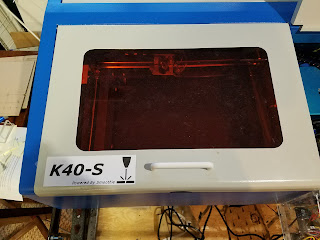
Status is: IN DESIGN
There are two panels in the K40-S build configuration.
The rationale for using two panels is in the index
For other information on the K40-S build use the K40-S BUILD INDEX with schematic
Donate:
Please consider donating (button to the right of this post).
Your donations help fund additional research, tools and parts that I will return to the community as information
The K40-S operations panel
The operations panel for the K40-S provides laser, temperature and power control functions.
It is designed as a drop in replacement for the stock panel.
Mapping K40-S functions to stock panel:
Power: uses stock switch
Fire: same switch as "Test Switch"
Enable: same switch as "Laser Switch"
Meter: same as stock current meter
Current preset: digital meter added with "Current Regulation" pot below it.
Water Temperature: added digital metering (see schematics for part #)
Armed: The "Armed" light is part of the interlock circuit and illuminates if the "Enable" button is asserted and all the interlocks are closed.
Mechanical Design
The mechanical design is here:
 |
| 1-1 cardboard model installed to test fit |
 |
| Figured I would add a logo while I am at it! Will be printed on sticky back something |
Digital Relative Laser Power Setting
This digital meter give you a digital value for the pots position. I makes is easier to read the posts position and reset it to the same position. Its called "Current Preset" in the above design.
A three wire digital voltmeter is necessary.
Add A New Pot For Finer Control
This pot is a replacement for the stock one and provides improved resolution and linearity. https://www.amazon.com/gp/product/B00VG93UD8/ref=oh_aui_detailpage_o01_s00?ie=UTF8&psc=1
Enjoy and comment,
Maker Don

Hello
ReplyDeleteThank you for all the info you've compiled here! Amazing!! I'm trying to install dvm and pot on my k40 and have run into a head scratcher.
Dvm- dsn-dvm-368 3 wire
Pot- 3590s-2-103L 10 turn
Lps- jg-40w (has green 4 pin on left with mains, 3 small white plugs, 4 pin white on right) k+k- is reversed on mine.
I'm replacing the digital panel powerLED v3.5
I have my pot and dvm wired as you show from plug (G,in,5v)
Pot is pin 2,1,3 -> shaft
5v to pot pin 3 (closest to shaft) and red on dvm
In to pot pin 2 wiper(opp shaft) and white on dvm
G to pot pin 1 (middle) and black on dvm
Power on results in variable output to laser controlled with pot. I can see on my analog ma meter.
No display on dmm
I can test with multimeter at contacts on dmm and get 5.09v and variable on white at dmm. Just no display. If I power off lps and supply 5v from external source to pot pin 1&3 the dmm lights and shows variable voltage as pot turns.. like it should. For the life of me I cannot figure out why the 5.4vdc from external source lights the display and the lps 5.09vdc doesn't light the dmm. This dmm says the lowest measurable voltage with white and red shorted is 4.7vdc. so 5.09vdc should work in 3 wire mode.. but it don't. I have 2 of these dmm's and both work outside the laser but neither in.
Any suggestions?
Thank you
Update:
DeleteI just discovered that if I use a heat gun from my soldering station and warm the display just a bit, it comes on... I have 2 of these displays and they both do the exact same thing. Same results using 2 different power supplies.. both 5vdc... Btw it's 84°F in my shop so cold isn't a factor...