
K40-S endstops
I am working toward an upgrade on my K40 to a smoothie (K40-S). I could not find any wiring /schematic information on the optical end-stops that are in my version. I guess some units have optical interrupters and some have micro switches, mine is optical.
The BUILD INDEX with schematics
The BUILD INDEX with schematics
Donate:
Please consider donating (button to the right of this post).
Your donations help fund additional research, tools and parts that I will return to the community as information and how-to's.
Problems with end-stop alignment
Be careful when re-assembling the daughter card and installing it on the gantry left the sensor so that it would hit the interposer in the back. The interposer is not adjustable and mounts from the back of the gantry. The sensor daughter board has no adjustment either. I could get it to barely clear the interposer if I forced the board to the left. Not good, looks like I will have to file some slots in the sensor mounting plate.

I slotted the holes in the end stop mounting plate.

Then aligned the interposer into the middle of the optical sensors gap. The alignment took patience and multiple attempts but it is better placed.

Schematic of End-stop Daughter-card

The daughter card assembly and dis-assembly
I captured views of the assembly so I could return it to original once I got a wiring diagram/schematic complete. I also marked orientation of the connector and cable with black dots.
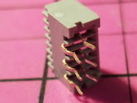
The daughter card has has 2 FFC style connectors one 12 pin and one 6 pin.
The 12 pin connects to the K40 controller board and the 6 pin connects to the horizontal end stop daughter board which is under the x axis carriage. Since I only needed the pin-outs for the daughter card I did not remove the horizontal board as I assume the sensors work the same.
The daughter board is mounted to a bracket that is screwed to the left back side of the horizontal carriage assembly.


Daughter card diagram
This is a drawing in a perspective from the top of the board. I will add all this to the K40-S (Smoothie) as I complete the conversion.
Connections to Middleman board:
Be careful with the cable orientation and installation of the FFC connector in the middleman, it matters.
The white flat cable can only be put into the FFC connector one way, one side is not conductive. This is complex to explain, but to keep the cable flat (not a twist) the pins are reversed from one end to the other. This means that what is on pin 1 on the middle man board is on pin 12 on the end stop breakout. I pulled mine out of the machine and checked it to be sure.
More on this: K40-S Middleman Board Interconnect
More on this: K40-S Middleman Board Interconnect
 |
| FFC cable orientation |
End-stops Interface to Smoothie
Optical End-stops
The figure below shows the equivalent circuit when connecting optical end stops to the Smoothie.
When the sensor is interrupted the receiver is off and the transistor is off leaving the input to the Smoothie at 5VDC. (the Smoothie's default pullup connection for R7 is to 5VDC)
The configuration file must be set up correctly for a HIGH true end stop condition.
 |
| A typical input circuit when connecting to Xmin-max, Ymin-max. Ignore the J designations. |
My Optical ENDSTOP Config
My configuration changes as I learn new things and complete testing.
Check my current file here
## Endstops
endstops_enable                              true
#corexy_homing                               false
alpha_min_endstop                            1.24^
alpha_max_endstop                            1.25^
alpha_homing_direction                       home_to_min
alpha_min                                    0
alpha_max                                    200
beta_min_endstop                             1.26^            #
beta_max_endstop                             1.27^            #
beta_homing_direction                        home_to_max      #
beta_min                                     0                #
beta_max                                     200              #
gamma_min_endstop                            1.28^            #
gamma_max_endstop                            1.29^            #
gamma_homing_direction                       home_to_min      #
gamma_min                                    0                #
gamma_max                                    200              #
alpha_max_travel                             500
beta_max_travel                              500
gamma_max_travel                             500
Mechanical End-stops
The Smoothie end-stop input circuit is the same whether Optical or Mechanical.Configuring the switch so that when closed it provides a HIGH to the smoothie input would look like the optical end-stop and use the same configuration. In this case you would use the NC connection of the switch to ground. This means that in normal operation the switch is drawing a small amount of current all the time form R7.
Alternately you can set the switch up for NO with a grnd from the frame. In this case you set up the Smoothie configuration for LOW true.
Hybrid Endstop configurations
I see no reason why optical and mechanical endstops cannot be mixed provided they are wired and configured as above
Repairing/replacing your sensor & potential design problem
Helping another K40 owner with a end-stop sensor problem (standard Moshi board) I ran into what I believe to be either a design problem, a part incompatibility or both.The problem started when the Y endstop optical sensor was damaged by misalignment and was subsequently replaced with a new TCST 1030. From that point on the machine did not operate properly having difficulty homing and other movement issues.
After replacing various parts including the Moshi controller the owner sent me the entire end-stop assy.
Troubleshooting
I hooked my end-stop tester up to the assy and immediately it was apparent the neither axis optical sensors was working.Middleman as an endstop test board
What do you do with an extra Middleman board?Build an optical end stop tester .... of course !
Schematic is here with use instructions:
http://www.digikey.com/schemeit/project/k40-endstop-tester-L91LPBG2001G/
Package is here, nothing impressive. It uses 2x 2016 button batteries and holder a PB switch and 2x LEDs. :
https://goo.gl/photos/TatG7gw7LjWsMtgSA
Video of use is here:
https://goo.gl/photos/MDxDGBuseskPnTGS9
Note: if you don't have a Middleman board you can make one of these using a FPC connector whose pins are soldered to the battery, switches and LED's see the schematic for wiring.
G+ linking the tester
X end-stop
I found that the 6 pin ribbon cable had an intermittent and after learning that you can't buy "just one' of these I repaired the condition by adding layers of scotch magic tape to the cable. That thickened the cable and improved the contact between the cable and socket. I added hot glue as an added measure.


Y end-stop
The Y end-stop was working but the output transistor was not fully turned ON leaving the ON condition at more than 3V and the off condition at 4.9V, certainly not a legitimate logic switching level.
I checked and tried everything including replacing the sensor. Nothing worked to improve this marginal condition and the wiring was sound and the components were the right value.
The only difference between the X and Y optical end-stops was that the Y one had a new sensor.
The design problem
One or both of the following conditions cause the problem manifested in the Y axis above:- The CTR for the stock TCST 1030 and the over the counter part are different.
- The current limiting resistor (1000 ohms) in the stock design creates an operating point (3-4 ma) that is in the non-linear part of the CTR curve.
A better value is 100 ohms which runs the emitter at 37ma and further up the curve where it is flat.
The max current for this device is 60ma so this operating point was judged to be safe.
This change was tested and resulted in these sensor output values:
- On = .5
- Off = >3VDC
 |
| CTR for TCSt 1030 |
The fix
If you have to replace the stock sensor then likely you will have the above problem.
Therefor you may also need to replace the 1K resistor with a 100 ohm resistor at the same time.
 |
| End-stop daughter card with 100 ohm resistor |
Optical End-stop Reliability
I have heard of K40 users having reliability problems with optical end-stops. I was surprised to hear this since I had used them in many devices successfully. They however have to be designed properly.
The marginal operating point identified above could be the cause of these problems.
1x 1000 ohm 1/4 resistor
1x Optical sensor:
1x 6 Pin connector

Optical Endstops Parts List
X-Y Daughter card
1x 12 position FFC. 1.25mm ribbon connector1x 1000 ohm 1/4 resistor
1x Optical sensor:
- Replacement sensor: TCST 1030, Purchase, Data Sheet
- Purchase, Data Sheet Note: this is an alternate connector that I think fits but have not tried it.
X Daughter card:
1x 6 position FFC. 1.25mm ribbon connector1x 6 Pin connector
- Purchase, Data Sheet Note: this is an alternate connector that I think fits but have not tried it.


FFC Cables
1x 12 position FFC. 1.25mm ribbon 46" long- 12" Purchase, Data Sheet Note: would need to piece together and min order qty =1000 :(
- 12" Purchase, Data Sheet Note: Use and move the middleman board into the bay next to the Y gantry. I have not tried this.
- Purchase,Data Sheet Note: 1000 unit min purchase qty. :(!
- Use, Purchase, Data Sheet and slide out 6 postions
K40 Endstop Models
SketchUP models of the K40 endstop daughter-cards are here:https://3dwarehouse.sketchup.com/model.html?id=f71480c9-a4b5-4f11-90de-0b77e8e9a6c4
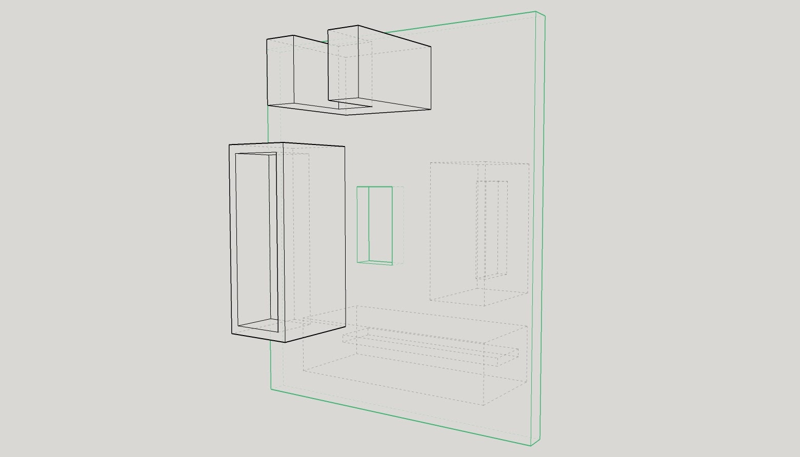 |
| x-y end-stop model |
 |
| X end-stop model |
Mechanical End-stops
This looks like a simple way to create mechanical end-stops without much mechanical modifications.More Information
I found this build log that helps provide information on the x axis daughter card and how this maker made K40 mods:My Y axis is stepper17HM4410N-03AD-Z. I will link this to a future blog entry on steppers.
http://www.mecheltron.com/en/product/42bygh-stepping-motor
Enjoy and leave comments if you have suggestions or corrections
Maker Don
Hi Don,
ReplyDeleteI had problems with my k40 with it not homing in the top left, it would keep on coming till it bottomed out and stalled.
But thanks to your suggestion of changing the resistors to 100 ohms it now works as it should.
thanks Don
Regards
David
Hi Don, my K40 suddenly after one month of good use is behaving erraticaly. Once turned on it tries to home away from the Y endstop. X carriage also does weird things. Its strange because yesterday it was working nicely. Should i replace both 1k resistors for 100ohm ones in both endstops? Thank you
ReplyDeleteCheck that the metal flag is not bent and fully engages into the optical sensor without hitting it.
ReplyDeleteIs the sensor damaged? If so replace it and the resistor.
You should not have to change the resistor unless you have just changed the sensor component. That said if nothing else work replace the sensor component and resistor.
Hey Don, i want a optical limit switch complete set where can i buy it.
ReplyDeleteHi Don - That link for the Thingiverse endstop homed at the bottom left - how would that work?
ReplyDeleteHi Don, just wanna take the time to thank you! I busted the Y axis optical switch while I was servicing the machine, so I replaced it with a new one, but like you said, it wouldn't work! I had no idea what it was, Checked every cable, I clean the board, nothing worked, thanks to your post I realize I had to change the resistor, worked like a charm!! Now it's working just fine! I might make a video for YouTube, because I notice a lot of people having the same issue but I couldn't find an answer on any video, I will give you the prompts of course, and send them here to your blog, thank you again, people like you inspire me to keep learning.
ReplyDeleteHelp mine is broken where can I buy x and y replacement switches cant find any anywhere
ReplyDeleteHi, you can buy them now at dashy.tech
Delete