INSTRUCTIONS:

Check out the new MoBeam posts! To find K40 conversion information use the "INDEX", "SEARCH" or "LABELS" sections in the sidebar.

Sunday, January 29, 2017

When the Current Regulation Pot Fails!

Background

When your "Current Regulation" pot fails there is a better part to replace it with.
This new pot is $6.99 and features 10 turn linear resolution with a smooth rotary action.

Donate:

Please consider donating (button to the right of this post).
Your donations help fund additional research, tools and parts that I will return to the community as information.
For other information on the K40-S build use the  K40-S BUILD INDEX with schematics

THE FAILURE

The wipers fold back.
I guess I turn the pot to fast!
There are supposed to be multiple wipers. 

THE FIX

Getting the knob off was a B*%^+. I had to grab the shaft with a vice grips. Then wedging a flat blade between the vice grips and the knob I pried it off. I think the knob was glued on ..... seriously!

After the gripping experience with the knob the rest was easy. Simply wire in a new pot.
This one is a linear multi-turn wire wound pot which gives much better current resolution and feels nice!


Purchase here

Note: these pots are often not avialable. Any 5K pot will work. The 10 turn ones give you finer control.

Wiring & Diagram

The replacement is pretty simple if you pay attention to the pots connections when you take the old one out. The only confusion might be that the new pots connections are not in order. The wiper is the first pin (2) from the end opposite the shaft.
If the pot operated backward reverse the leads 1&3.

Here is some help ....

Careful the wiper is on the left.

Pot with DVM current readout
I wired in a plug to make disconnect easy and modular

Installed in the panel 


DVM

I added a DVM across the pot so that I could get a digital representation of the pots postion and the relative current. 
When setting up a job type I record the digital value and then next time I do that same job I just reset the pot to that value to accurately repeat the setting.


Note: you need a 3 wire DVM so that you can read from 0.

See the wiring diagram above for installation.


The green film in this pack works for a filter when making a plastic bezel .

KNOB

This knob might look nice and installs with a set screw.

Purchase here


Enjoy and comment
Maker Don

Saturday, January 28, 2017

K40 LPS Configuration and Wiring

Background

This post captures the many K40 PS configurations that I am/have worked on.

READ THIS POST if you want to know about how to digitally control a K40 LPS: 

I need Laser Power Supply's (LPS) (dead or alive) to test:

If anyone has a LPS schematic or a blown LPS that we can use to better understand its interface please contact me at: don_kleinschnitz@hotmail.com or comment below.

Donate:

Please consider donating (button to the right of this post).
Your donations help fund additional research, tools and parts that I will return to the community as information.
For other information on the K40-S build use the  K40-S BUILD INDEX with schematics

Reverse engineering Information:

From Scott Marshall on G+:

This is the manufacturers page there's specs and such there, minimal, but some info.
http://en.jnmydy.com/products_list.html
http://en.jnmydy.com/comcontent_detail/&FrontComContent_list01-1285720952066ContId=4&comContentId=4&comp_stats=comp-FrontComContent_list01-1285720952066.html

Inputs P+ and K+ directly drive these optos:http://www.everlight.com/file/ProductFile/EL817.pdf

Driving this PWM Controller by good old Texas Instruments
http://www.ti.com/lit/ds/symlink/tl494.pdf


Inputs are speced at 5v, but look to work on 3,3v (show 3v logic High)

It's pretty conventional switching supply stuff from there. The Hv circuit seems to be a flyback running at about 440hz (awful low) with a tripler output.
300W 11kv nominal 4-20ma (26kv insulation breakdown)

Measurements

Shown in "[approx value]" are the measurements taken from my machine as a help in troubleshooting.

These measurements are approx and your actual readings may vary.
However if they are way off that may be an indication your have a problem.

BTW: wire colors also match my machine but yours may be different.

AC Power Connector

Not always in this order
  • -L (cathode of laser) [0 ohms to frame and to cathode of laser]
  • FG (frame ground, directly connected to frame)[0 ohms to frame]
  • AC (one side of main power)*
  • AC (other side of main AC power)*
* measured AC across the mains = [whatever your mains volts is]

 DC Power Connectors:

The DC Power connector on the LPS typically contains these signals:

[* ] = measurements with DC connector disconnected
  • 5VDC (Yellow) [*5VDC to frame & gnd]
  • GND (Black) [*0 ohms to frame]
  • 24VDC (Green) [*24VDC to gnd and frame]
  • L (Pink) (the M2 Nano LO pin connects to this pin in stock K40's) [*4VDC]

DC output capacity specs:
  • 24v@ 1 amp
  • 5V @1 amp

General LPS specs for GWWG LPS from ebay:

Taken from ebay site

Understanding K40 Laser Power Supply Configurations

To effectively test, repair, replace and convert K40 LPS it is necessary to know that kind of supply you have.
This section attempts to identify and categorize the LPS I have encountered. There are two parts to identifying the LPS:
  • Physical Configuration
  • Control Schema
An example configuration might be: GGGR-A. The notation is explained below.

Power Supply Physical Configurations:

Key to my physical configuration labelling

First Letter: color of AC power connector
Second Letter: color of control connectors
Third Letter: color of DC power connector
Fourth Letter: color of Power LED

Physical Configuration GWWG

Label on back of my LPS supply, I got to it with a video borescope :)
Ebay: MYJG40 (first time I have seen one like mine for sale)

MYJG40W [S/N: 2015090481]


Mine looks like this (I think this type is out of production): 

Physical Configuration GGGR

Photo:

Laser Power Supply (LPS) Control Interface Schema's

K40 LPS typically have either 1 green 6 pin connector or 3 white connectors for control (located between the AC and DC connectors. In all cases some combination of their signals perform the same basic functions of:

  • laser enable 
  • laser
  • analog power control. 
To make things more complex in some configurations the 6 Pin green connector contains different control signals than other green connectors with the same pin #'s. For that reason along with the physical configuration it is necessary to know what control schema is used.
The basic way these signals are used is shown in the sketch below.

Showing the interface equivalent circuit.


Control Schema Labels A-C

I arbitrarily labeled the two types of control interfaces "A" - "C" to simplify the documentation.

Type "A"  LPS Control Schema

This is a common K40 supply and is usually physical configuration GWWR or GWWG.
This schema uses 3 separate white connectors in the order below from left to right.

Laser Switch (enable)

  • P+ Laser Switch [**4.28VDC]
  • P- gnd return for Laser Switch [0 ohms to frame]

Test Switch ("FIRE")

  • K+: Test switch [**4.28 VDC]
  • K-: gnd return for laser [0 ohms to frame]

    Current regulation

    • Ground: signal ground [0V to frame]
    • IN: laser current control 0-5VDC [**not sure, likely floating]***
    • 5VDC: 5V power [** 5.02 VDC]
    Note: the "Current Regulation" pot is connected across these three signals with the center tap connected to IN.
    *** you can partially test "IN" by measuring the resistance across IN to gnd while turning the Current Regulation POT on the panel. The resistance should vary with pot position.

    ** voltage measured with connectors removed

    Type "B" LPS control interface

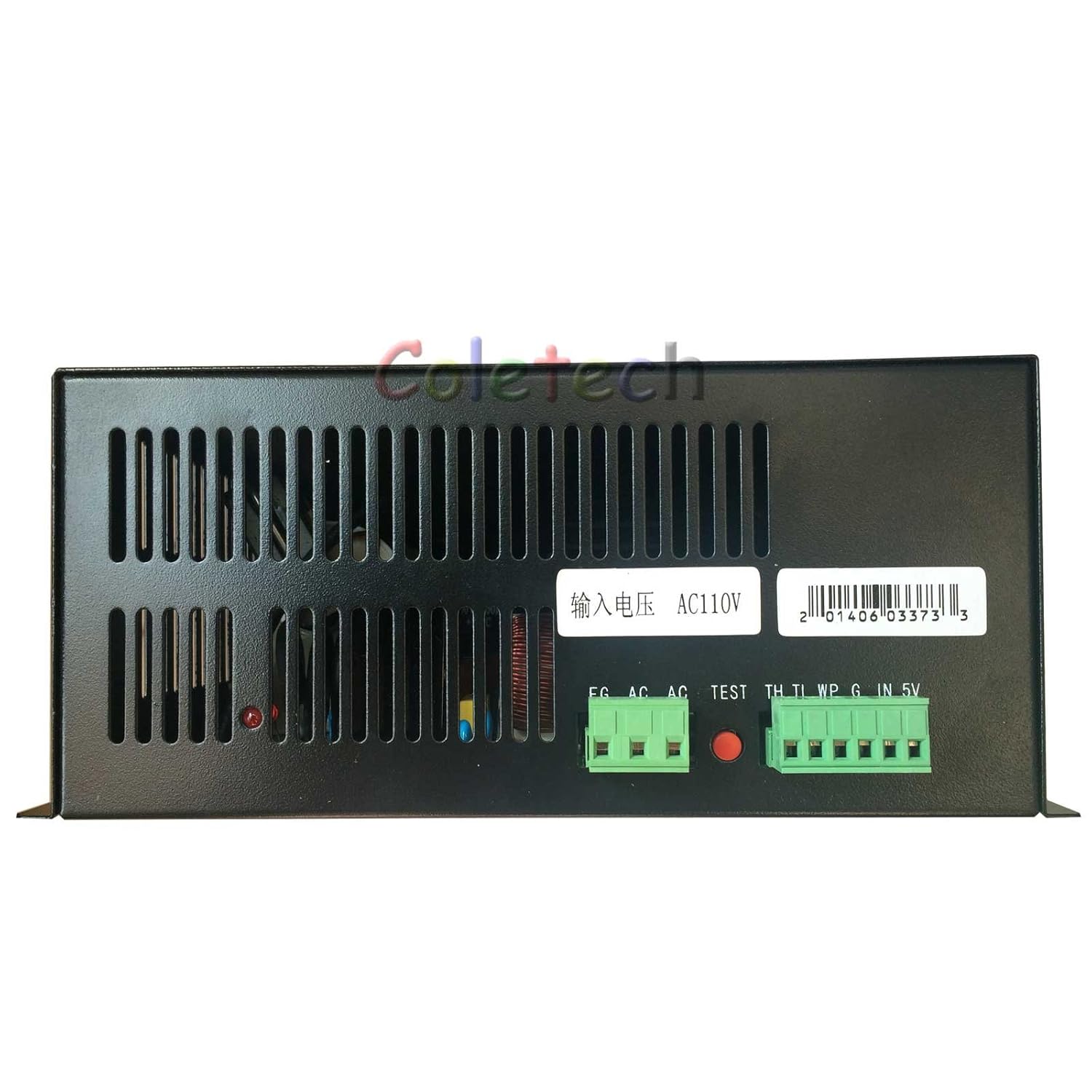
    These supplies often have black cases and sometimes have only the control and AC connectors. They usually do not provide DC power.


    Terminal Definition as follows:

    THInput SignalOn-Off laser control,TH≥3V, emitting laser; TL≤0.3V, no laser.
    TLInput SignalOn-Off laser control,TH≥3V, no laser; TL≤0.3V, emitting laser
    WPInput SignalOn-Off laser control,TH≥3V, no laser; TL≤0.3V, emitting laser
    GGNDThis foot must be connected well with the laser machine shell and the ground of control board.
    INInput SignalThe control of laser power: Both 0-5V analog signal and 5V PWM signal can control the laser power.
    5VOutput PowerOutput 5V, the maximum output current is 20mA.

    Note: WP = water protection, this is an interlock loop for the water pump.

    Type "C" LPS Control Interface

    I think this is the configuration that ships with newer K40's.

    Type D Control Schema

     Same schema as a Type A but a "D" signal replaces the "P" and works the same.


    Special LPS Wiring

    Special wiring for this supply, note part # at top of drawing


    Converting From One Supply Type to Another

    Conversion of GGGG-C to GWWR-D

    LPS Related Album


    Enjoy and comment
    Maker Don

    Saturday, January 14, 2017

    Laser Specific G & Mcodes

    Background:

    This post captures G and M codes that are specific or that have modes or options that are specific to Laser machines.

    Donate:

    Please consider donating (button to the right of this post).
    Your donations help fund additional research, tools and parts that I will return to the community as information.
    For other information on the K40-S build use the  K40-S BUILD INDEX with schematics

    Special K40-S Gcode formats

    Adapted Gcodes for K40-S follow.

    The G01 command

    G01 <X Y F S>
    • X- x position
    • Y- Y position
    • S- Laser power in decimal from 1(max) - 0(min)

    Currently Unsupported LaserWeb Gcodes


    G20 will be ignored and all values will be interpreted as metric. Example: 1" will render as 1mm

    Mcodes (Machine options)


    Laser Mode : 

    The new "laser" mode will cause Grbl to move continuously through consecutive G1, G2, and G3 commands with spindle speed changes. When "laser" mode is disabled, Grbl will instead come to a stop to ensure a spindle comes up to speed properly. Spindle speed overrides also work with laser mode so you can tweak the laser power, if you need to during the job. Switch between "laser" mode and "normal" mode via a $ setting.

    Dynamic Laser Power Scaling with Speed : 


    If your machine has low accelerations, Grbl will automagically scale the laser power based on how fast Grbl is traveling, so you won't have burnt corners when your CNC has to make a turn! Enabled by the M4 spindle CCW command when laser mode is enabled!

    Reference: https://github.com/gnea/grbl

    Tuesday, January 10, 2017

    K40-S configuration

    Smoothie Configuration

    This is a clone of what I am currently running for my K40-S configuration

    I am in the middle of TEST so all these are not final.

    Donate:

    Please consider donating (button to the right of this post).
    Your donations help fund additional research, tools and parts that I will return to the community as information.
    For other information on the K40-S build use the  K40-S BUILD INDEX with schematics

    Links to important configuration definitions

    Smoothie configuration options
    http://smoothieware.org/endstops

    Updates to the Configuration:

    Alpha & Beta steps/mm

    • was = 315.5
    • should = 157.575. Otherwise, files cut at 2x their size

    *Laser PWM setting for better engraving.


    laser_module_pwm_period                      200              # this sets the pwm frequency as the period in microseconds

    *These changes are not in the configuration file below:

    My current K40-S PROTOTYPE configuration

    https://drive.google.com/file/d/0B9A1NYiboK99VEthU1NYMGxLbFk/view?usp=sharing

    Other Configuration information:

    • Motor Current 1.0a, 157.75 steps per mm, Laser Module - true,.
    • (just discovered 1st & 2nd Hotend is default true. Changed to False),
    • Switch Misc changed to false (using 2.4 for Fire),
    • TempSwitch enable - false.
    • driving the steppers 1/32 really quiets down the machine and makes it seem a lot smoother.


    K40 Optical Path Improvements

    Background

    As my K40-S conversion matured I started to actually use the machine to make parts, mostly from acrylic.
    As I learned the nuances the optical subsystem I found areas for improvement and they are logged here.

    For other information on the K40-S build use the  K40-S BUILD INDEX with schematics

    Donate:

    Please consider donating (button to the right of this post).

    Your donations help fund additional research, tools and parts that I will return to the community as information 

    Optical Path

    Elements of the K40 optical path

    • Laser
    • #1 mirror
    • #2 Mirror
    • #3 Mirror
    • #Objective lens
    I also felt that some of the optical mounts were unstable and required to much effort to access them.
    I decided that if I was to make improvements the optical path while making it easier to align then I needed to model the real system.

    The model that I am working with is outlined in this post:
    https://3dwarehouse.sketchup.com/model.html?id=385d6821-536b-413b-870e-5d4502ce1e0e

    My goals for this activity are:

    • Improve the stability of optical mounts
    • Make alignment easier
    • Design as much as possible so that it can be built by hand and laser in the shop

    Laser Head Redesign

    Old Hack

    When I got the LO air assist I had to re-make the objective lens mounting plate to fit the LO objective lens mount. Later I also hacked in a:
    • Finder LED
    • Drag chain bracket
    The hacked head was pretty ugly and because it had brackets stacked on top of each other it was hard to align. I also thought my drag chain bracket was marginal.
    The ugly old heavily modified head


    The new design has:

    • All plastic laminate construction for weight and stability
    • More reliable and plugged connections to the finder.
    • Azimuth screw adjustment on the finder laser, instead of bending a metal bracket 
    • Locking screw on finder laser.
    • Integrated drag chain bracket.
    • Requires about 2 hrs of manual shop time or laser cut capable.
      • The large holes can be drilled using 1" and 3/4 inch forsner bits.


    Laser Head

    The model provided the ability to get key dimensions relative to the opto-mechanical components.
    • Lense FL = 38.1 mm
      • Distance to surface from head w/o assist cone installed
      • Distance to surface from head with assist cone installed

    Model of head


    #2 Mirror Stability Improvements

    While running ramp tests I found that my #2 mirror would not hold its alignment.
    I found a defect in the way it was manufactured. The adjustment screws each have a detent into which the screw is seated. These detents align the face frame that holds the lens. The upper left adjustment screws detent was improperly drilled allowing the screw to pop in and out of position, changing the mirrors alignment. 
    The solution was twofold.
    1. Re-drill the hole so the adjustment screw has a positive detent. Unfortunately the original hole was drilled only slightly off and the drill bit wanted to wander from the new hole position into the original hole. After disassembly I clamped the frame in a vise and first drilled a small pilot hole. Then carefully drilled using successively larger bits until the final which was 7/64".
    2. After reassembly I noticed that the outer frame was only held fast by the tension of the springs. I didn't like that design and wanted a more positive way to insure the mirror does not move under vibration. My solution was add a locking screw to the assembly to insure that the mirror frame cannot move once adjustment is made. I used a 4-40 Philips head screw and star washer.
    3. I think I found a way to make the mirror mount position adjustment, on the mirror bracket (underneath) accessible. To properly adjust I found that I had to remove the bracket, make the coarse adjustment and then reinstall multiple times to get the bracket in the center of its adjustment range and then do the fine adjustment from the topside using the brackets mounting screws. I added two thumbscrews that are accessible underneath with your fingers allowing you to loosen and adjust without having to use a screwdriver while blindly hunting the screw heads.

    Underside Adjustment Modifications

    Simple, just buy and install these thumbscrews :)
    https://www.mcmaster.com/#92581a120/=15upn2q

    Before...


    After .....

    Making the locking screw modification:

    1. Remove the lens
    2. Clamp the assy. in a drill vice
    3. Choose a bit sized for tapping whatever size screw you are installing. I used a 4-40 so the drill was #43. A #2-56 probably would be better.
    4. Drill the hole that is square to the surface in approx the position shown in the pictures below through the front and back frame. I drilled from the back side and I drilled with it fully assembled so the front and back frames were aligned. For me the location was .5" from the top left and .14 from the left edge. The position is not critical just insure that it does not interfere with the adjustment screws or the mirror retention face frame.
    5. Tap the hole in the rear frame. The screw will enter from the front and screw into the back plate. The front plate will not be threaded.
    6. In the front frame re-drill the hole to provide a liberal clearance hole for the screw size you are using. The intention is to insure that when the lock screw is loosened for adjustment that the frame does not bind on it. 
    7. Install the locking screw and washer.
    8. Install the lens and its keeper.
    9. Reinstall in machine and align.
    Note: I replaced the spring retaining pins with more robust dowel pins. I also fabricated a wrench to make tightening the adjustment screw nuts easier :).

    Locking screw cams the frame out of alignment

    Adding a plastic ferrule under the locking screw keeps it from cam-ing the frame when it is tightened and messing up the adjustment. I used a plastic spacer used to isolate screw when mounting PCB's.

    Note plastic washer under the locking screw

    To adjust the mirror with the locking screw modification.

    1. Loosen the locking screw by backing the screw out to its limit
    2. Loosen the adjusting screw locking nuts
    3. Adjust the mirror using the three adjustment thumb screws until you get the beam placement you want.
    4. Snug the adjustment screw locking nuts, don't over tighten. The screw is intended to limit the travel of the frame not distort it or pull the frame off its adjustment screws. Notice if the mirror frame moves when you tighten the screw if it does back off. 
    5. Recheck the beam position.
    The detent was drilled to the right of the adjustment screw. This allowed the frame to move left-right in-out of the detent
    New detent, drilled next to the misplaced one.

    The locking screw hole, below the upper left adjustment screw

    Locking screw installed

    Cross section view of locking screw. Do not use lock washer as shown here!

    complete ass and wrench

    Seriously, adjustments under the bracket :(

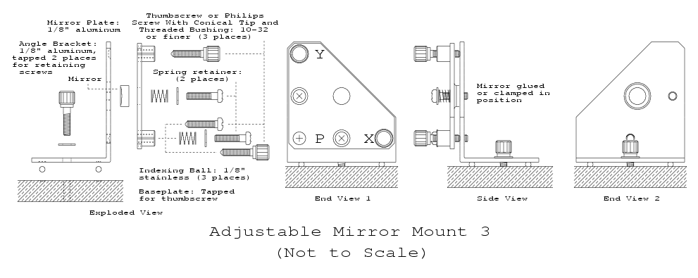
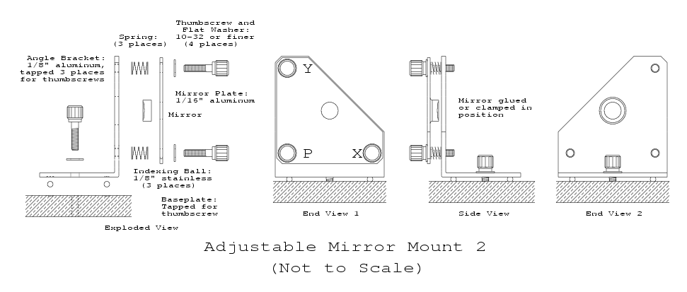
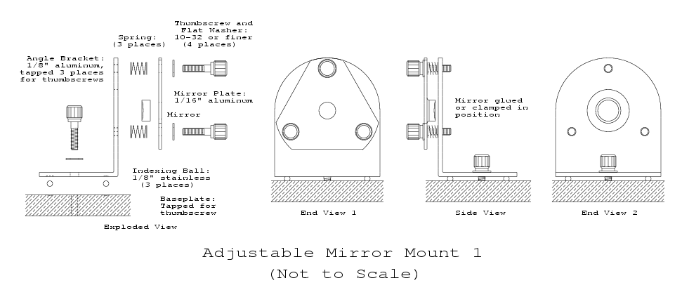
    Mirror Mount Designs

    Here are some links to DIY kinematic mirror mounts. I may use these as a reference for designing mounts that can be laser cut.

    https://www.repairfaq.org/sam/mmount3.gif

    https://www.repairfaq.org/sam/mmount2.gif
    https://www.repairfaq.org/sam/mmount1.gif


    Enjoy be safe and comment
    Maker Don

    Wednesday, January 4, 2017

    K40 LPS Replacement and Test

    K40 LPS parts and repair

    DON"T IGNORE THIS!

    WARNING: LASERS AND THEIR HIGH VOLTAGE SUPPLIES ARE BOTH ELECTRICALLY LETHAL AND OPTICALLY DANGEROUS. THEY HAVE THE POTENTIAL TO KILL AND/OR BLIND YOU
    1. STAY FAR AWAY FROM THE HIGH VOLTAGE SUPPLY'S OUTPUT!
    2. WEAR PROTECTIVE EYE-WARE AT ALL TIMES WHEN OPERATING A K40!
    3. DO NOT OPERATE A K40 WITHOUT THE PROPER LASER INHIBITING INTERLOCKS INSTALLED AND OPERATING PROPERLY!
    4. USE THE CORRECT HIGH VOLTAGE SAFETY PROCEDURES

    BY READING THIS POST YOU AGREE TO USE THIS INFORMATION AT YOUR OWN RISK!


    Most people are not skilled enough to be around and inside a high voltage power supply

     I DO NOT RECOMMEND THAT YOU REPAIR YOUR OWN LPS. YOU PROCEED FROM HERE AT YOUR OWN RISK!

    Donate:

    Please consider donating (button to the right of this post).

    Your donations help fund additional research, tools and parts that I will return to the community as information
    For other information on the K40-S build use the  K40-S BUILD INDEX with schematic

    Safety references

    READ THIS FIRST

    Replacing LPS as a Unit:

    Replacing the LPS is dangerous so adhere to all HV safety precautions in this post.

    Unplug your laser from the mains power and let it sit for 1 hr.

    Observe how the anode wire is connected to the tube including the wire routing and restraints.
    Install the new anode wire in exactly the same way.

    At the Anode end of the laser tube
    • Remove the silicon sheath from the anode connection. Minimize forces on the anode pin. It should pull off but if not you may have to cut it off.
    • Your anode wire may be twisted, screwed or soldered on the anode pin.
    • Remove the old anode wire. 
    • Replace the anode wire in the same way it was connected, twist, solder or screw.
      • If soldering use minimal heat. Some recommend using Teflon tape to hold wires that are twisted see video below.
    • Route and restrain the wire in the same way. Usually tie wraps around the tube moving away from the anode end toward the cathode end.
    • Flow silicon around the anode wire connection (use the white tube that came with your K40) 
    • Push the silicon tube over the wet silicon filling the tube. If you had to cut off the tube you will need to replace it with a peice of silicon tubing.
    • Add more silicon to the top of the silicon tube if needed
    • Let dry for 24hrs before using the machine
    Alternate silicon: Permatex Blue RTV Gasket Maker. Available in auto and big box hardware stores.
    703 adhesive silicone rubber insulation/potting/electronic waterproof sealant (the stuff that comes with the machine)

    The videos below for removing a laser show connection and disconnection of the tube form its supply and can be used as reference example:

    Laser Tube and/or Laser Power Supply Replacement Parts Kit

    A convenient way to buy parts for this replacement is to use this kit:

    Replacing the Current Meter & Pot 

    Current Meter

    This analog meters face is larger and has a larger mounting hole than stock: 
    There are many choices of cheap digital mil-lamp meters that could also be used in place of the analog one. Realize however, that it is harder to visualize fast moving current changes on a digital meter than an analog one. These meters also require a separate DC power source.
    Another reason that I like the analog over digital approach is that although probably overly cautious, I do not like the tube and its power supply connected in any way (dc power) into the same system as the controller. 

    Current Pot

    Links to LPS Repair Posts


    THIS IS NOT A RECOMMENDATION FOR YOU TO REPAIR YOUR LPS AND YOU DO SO AT YOUR OWN RISK!

    Testing Laser Power Supplies (LPS)

    Coming soon

    Schematic:

    The most recent schematic
    Some theory of operation if you like to know more about the circuitry. 

    Frequently failed parts

    • HVT transformer*: HVT choices are very confusing. There is a model A and and a model B type and they are different in how they connect to the PCB. There are two ways to connect to the PCB, with two bolts and with a 3 wire connector.When ordering from AliExpress you have to specify the right model so be careful.
    *It has been suggested that the HVT is the only difference between a 40W and 50W power supply. I have also noticed that higher power laser power supplies use multiple HVT to achieve their voltage.
    ** parts that I replaced in failed supplies

    HVT Transformer Testing

    This is an area of development. I am pretty sure that we cannot test HVT with conventional meters etc.
    I will update this area once I get a good and bad HVT to compare and test. 

    LPS Related Album

    Enjoy be safe and comment
    Maker Don

    Sunday, January 1, 2017

    K40-S Control Panels

    Status is: IN DESIGN

    There are two panels in the K40-S build configuration.
    The rationale for using two panels is in the index 

    For other information on the K40-S build use the  K40-S BUILD INDEX with schematic
    Donate:

    Please consider donating (button to the right of this post).

    Your donations help fund additional research, tools and parts that I will return to the community as information 

    The K40-S operations panel

    The operations panel for the K40-S provides laser, temperature and power control functions. 
    It is designed as a drop in replacement for the stock panel. 

    Mapping K40-S functions to stock panel:

    Power: uses stock switch
    Fire: same switch as "Test Switch"
    Enable: same switch as "Laser Switch"
    Meter: same as stock current meter
    Current preset: digital meter added with "Current Regulation"  pot below it.
    Water Temperature: added digital metering (see schematics for part #)
    Armed: The "Armed" light is part of the interlock circuit and illuminates if the "Enable" button is asserted and all the interlocks are closed.

    Mechanical Design

    The mechanical design is here: 

    1-1 cardboard model installed to test fit
    Figured I would add a logo while I am at it! Will be printed on sticky back something

    Digital Relative Laser Power Setting 

    This digital meter give you a digital value for the pots position. I makes is easier to read the posts position and reset it to the same position. Its called "Current Preset" in the above design.
    A three wire digital voltmeter is necessary.

    Here is how to connect it:


    Add A New Pot For Finer Control

    This pot is a replacement for the stock one and provides improved resolution and linearity.

    https://www.amazon.com/gp/product/B00VG93UD8/ref=oh_aui_detailpage_o01_s00?ie=UTF8&psc=1


    Enjoy and comment,
    Maker Don