INSTRUCTIONS:

Check out the new MoBeam posts! To find K40 conversion information use the "INDEX", "SEARCH" or "LABELS" sections in the sidebar.
Showing posts sorted by relevance for query control+panel. Sort by date Show all posts

Monday, February 26, 2018

Understanding the K40 Digital Control Panel???

K40 PowerLED Control Panel

Newer versions of the K40 sometimes ship with a digital control panel. This panel retains the main power switch but the Calibrate (potentiometer), Laser Switch, and Laser test buttons are replaced by push buttons and a controller PCB.

Warning: this vintage K40 control panel does not ship with a laser current meter. Therefore it is not possible to know the actual operating power the laser is running at a particular digital setting. It is important to monitor the actual running power of the tube during operation to maximize the tube's life.
All tubes will eventually fail and are generally considered consumable but their life can be optimized. Tube life is proportional to the running current* so setting the machine to run at the minimum current required for the job and staying under the tube's rating will optimize its life.

Some users have made the argument that although running the laser at higher currents may shorten the life of the tube it also shortens job time, so it's worth it.

Add a Laser Current Meter

I recommend adding a current meter to your machine if you do not have one. The meter will assist you in running your laser at a current that is consistent with optimizing its life consistent with your expectations.

Add an analog meter to your K40

Most manufactures specify their tubes reliability @ 1500-2000 operating hrs running a working current of 20-22 ma. Check your tube's specifications, especially if you have replaced the stock tube.

The longest life I have seen specified is:


* There are other factors such as shelf life and operating temperature that cause a laser tube to fail. 

Donate:

Please consider donating (button to the right of this post).
Your donations help fund additional research, tools, and parts that I will return to the community as information.
For other information on the K40-S build use the  K40-S BUILD INDEX with schematics

Thanks to +Chris Hawkins for donating a panel for this exploration

Testing

A donated K40 PowerLED V3.0 was bench tested using a simple tester made from a USB adapter a few resistors, a voltmeter, and connectors. This tester provides 5V through a USB brick and listens to the IN and P pins of the panel.
This tester was connected to the panel and various tests were performed as described below.


Schematic

The schematic of the panel and the test board as it develops is here:


Interconnection with the Laser Power Supply (LPS)

You will note that this control panel connects both the P + & P- of the panel to the K+ signal on the LPS rather than the P signals on the LPS. Wow, now that's not confusing :(.

Also, note that nothing is connected to K- on the LPS and P+ & P- on the control panel are shorted together.

A LPS wired to a K40PowerLED Panel note the 4 white wires (from panel) and the black wires (from water sensor)

Operation:

The PowerLED [as best I can tell so far] utilizes an embedded processor to provide the functions of the panel. The main functions of the panel are to set the power level of the LPS, enable the laser to fire, and test fire the laser. The indicators and controls include:
  • Laser power display
  • Laser Switch
  • Laser Test Switch
  • Light Instruction
  • 3X +/-Digit Controls: 10, 1,.1

Laser Power Display

Indicates the % of the power the LPS is set to. This display indicates the % of the LPS max power it is set to via the IN signals voltage on the interface. This display is operational as long as the Laser Switch is enabled.
The LPS power is controlled via an analog value of 0-5V on the IN pin of the LPS.

Laser Switch

This alternate action PB enables and disables voltage to the IN signal and the Laser Power Display. When this switch is OFF the display is off (except for decimal points). When the display is off the IN pin to the LPS is reduced to zero volts. When this switch is ON the IN signal will be a voltage proportional to the % displayed on the Laser Power Display.

Laser Test Switch

When this PB is pushed the +P/-P signal is grounded for as long as the PB is held. The Laser Test Switch grounds the +P/-P irrespective of the state of the Laser Switch. When this PB is pushed the "Light Instruction" LED illuminates.

Digit Controls

There are 3 sets of digit controls with a + and - control for each. These pushbuttons (PB's) allows the setting of the respective digit in the Laser Power Display.

Testing Data

The following spreadsheet contains:
  • A table of the IN voltage vs the digital % power setting taken during the test
  • The calculated error between actual and calculated power values for % settings.
  • A math model (equation) for the input-output function of the panel

Model: 

VoltsOnLPSIN = 2.4562 * (%PanelSetting^2) + (7.6189 * %PanelSetting) - .2686

R^2 = 99.69% (good fit!)

Plotted Test Data & Error Calculations

5vdc Power Supply Loading

This panel draws about .2 amps from the stock K40 supply. That's about 20% of the safe 5vdc capacity. Note that some new machines have an LPS with the fan missing. I have to believe that the stock LPS is running on its limit (1 amp w/o fan) with these vintage machines.

NEW! Go figure, the IN output is a PWM signal

After being prompted to dynamically look at the IN pin of the panel by +Lukas Bachschwell who showed us a scope trace of the signal I was surprised to see that these panels acutely drive the IN pin of the LPS with a PWM signal!!! Thanks, +Lukas Bachschwell

PWM signal on IN


As you can see in my test setup the power was set to 50% and the IN voltage read 2.9. The readings here are average since the signal is actually a PWM square wave. My cheap DVM read 2.9 (which we now know is an average) 

"IN" Scope readings

Vavg: 2.98VDC. 
Duty: 58.8 [*seems like an 8.8% error from panel settings to actual?]
Freq: 24.55kHZ

*it would be useful to test and plot PWM linearity, i.e. panel settings vs actual PWM DF.

Why is the "IN" pin driven with a PWM? 

Keeping in mind that the digital panel wants 
  • Digital control of the power by switch settings
  • Power value display
Since most embedded controllers have PWM capable outputs it's rational to use PWM rather than a D/A approach. The controller can manage the display, switches, and the power this way.

Can we connect our controllers PWM output to "IN" on the LPS

Yes. An open-drain could drive the IN pin on the LPS but in my assessment, it does not gain you anything that I can fathom and has downsides.

Should we use the "IN" pin vs the "L" pin for power control?

No. Although this is an ok way to control power locally between the panel and the LPS, connecting a controller to the IN pin is a bad idea because:
  • We need manual control of the power for testing without a controller connected. 
  • We need a manual offset adjustment. This allows us to avoid having to make job setting* changes to account for laser depletion. The laser wears over time and uses so the power setting for any given job will change over time.
  • The IN pin is not optically isolated from the HV supply but the L pin is. Using the L pin is close to the same as driving the IN pin but it's optically isolated.
*the software that is sending GCODE

Using both the "IN" and "L" pins give us good local power control as well as isolated power control from an external controller. 

 Assessment:

The display and controls worked as expected. See the graph for data on accuracy and linearity errors.
I felt the .1 digit was a bit overkill for a Laser Engraver as I think there are many variables in the process that are much larger than a .1% laser power change. I did not plot the tenths.

The % settings vs actual output voltage were pretty linear. The error increased to its largest value (10.15%) exactly at 50%  and then decreased until it reached 100%. I suspect this is related to the type of D/A that the controller employs (actually it's likely because the IN signal is actually a PWM).
From a practical perspective, the linearity error doesn't really matter. What is important is whether the panel can provide a full range of adjustable power from 0-100%. In normal use the operator adjusts the power to suit a particular job noting the best setting and as the laser "wears" that setting will change anyway.

During testing, I noticed that sometimes the % value would decrease when the + key was pressed and sometimes it did not recognize a keypress. More of a nuisance when setting the power but a safety issue if the Laser Switch behaves that way.

Safety

My biggest concern is how the laser is enabled. The embedded controller apparently reads the Laser Switch (the fact it is a momentary PB yet operates as an alternate action switch is the giveaway) and sends the set voltage to the LPS.
If the Laser Switch is alternated to the OFF position it puts 0V on the IN pin and this is the only way the laser is "turned off". Essentially the laser is enabled, just at 0 power. I guess that is not theoretically different than disabling the power with one of the other enable functions (K or P) but it just feels wrong to me. It's reducing the power NOT disabling the LPS.

Let's consider how this safety mechanism can fail:
  1. A firmware bug does not turn off the IN voltage when the Laser Switch PB is alternated. Example: a bug turns off the display but leaves a voltage on "IN".
  2. The firmware does not recognize an alternate push of the Laser Switch and does not turn off the IN voltage. The operator does not notice the display is ON and thinks the Laser Switch was pushed. I have noticed during testing that sometimes the +/- keys and the Laser Test Switch does not work. The switch seems to be intermittent or the firmware is missing the press. 
  3. There is a failure on the control panel electronics that keeps the IN pin at a voltage.
  4. Somehow a voltage gets on the "IN" pin from somewhere else in the machine's circuitry there is no secondary means of inhibiting a beam.
  5. The display being ON or OFF is a confusing way to tell the operator the state of the "laser enabled" function. In most machines, the display turns on when the power turns on and stays on during operation. A specific indication that the laser is enabled is more appropriate. 
  6. Example dangerous scenario: the laser is enabled and the operator pushes the Laser Enable button, the display turns off but the IN voltage is left at whatever value it was before. The operator thinks the panel being off means the machine is powered off. During troubleshooting inside the covers, the operator starts a job ...... the laser is now active.
I doubt that this kind of circuit strategy for making a laser safe would be considered "fail-safe" according to OSHA regulations.


  1. Under the requirements of the ANSI Z 136 Standard, for embedded Class IIIB and Class IV lasers only, the interlocks are to be "fail-safe." This usually means that dual, redundant, electrical series-connected interlocks are associated with each removable panel.

Definition of a Fail-safe Interlock
An interlock where the failure of a single mechanical or electrical component of the interlock will cause the system to go into, or remain in, a safe mode.

Editorial Comments

Safety

I am not under any illusion that the K40 is SAFE as shipped although I do wonder what the FDA symbol on the K40PowerLED panel infers???? That said, I endeavor to follow OSHA and FDA recommendations whenever possible while doing conversions. This is to enhance my own safety and the safety of those mimicking my builds. To that end my machine has interlocks. These interlocks are not in series with any firmware and consist of nothing but wire, connectors, and mechanical switches. They all fail in the disabled mode...

For those using this panel; ensure that you install interlocks on all accessible covers using the P+ loop on the LPS. Put front and rear cover interlocks in series with the water-flow switch. 

Operation Improvement

The K40PowerLED panel would at first glance present itself as a high-tech implementation of K40 control. In my assessment, it does not provide much if any, advancement in the operation of the K40. In fact, the missing laser current meter makes an important operational measurement invisible to the user. Running overcurrent is the fasted way to shorten the life of a tube. Without a substantial improvement in functionality I am not willing to take the safety risk I think this panel may present.

The Good!

  • You can see a digital display of the % of max power the laser power is set to.

The BAD!

  • The buttons do not always respond or respond correctly
  • The panel draws an additional 20% of the already loaded 5V supply
  • No laser current meter leaves the operator blind to laser tube stress
  • Less linear than a linear pot 

The UGLY

  • Potential safety hazard in that the laser enables indication is confusing and the circuitry is not fail-safe.

Next steps

I do not think that further exploration into this panel will reveal more than the actual design that was used.
I am noodling if a safer, and more comprehensive control panel is wanted, needed, and cost-effective to improve the operability and safety of K40 conversions. Let me know your opinion in the comments..

Enjoy,
Comments and corrections expected;
Don


Monday, February 4, 2019

K40 Laser Power Control Characterization

Laser Power as a Function of Operator Controls

Recently +Ned Hill replaced his digital control panel with an analog one.
In the process he was thorough enough to take some measurements of the digital panels effect on laser power. Since Ned replaced the laser and the LPS this data may well describe an ideal K40 machine.
  • %PWM, 
  • Control Voltage (on the LPS-IN pin)
  • Laser Current 
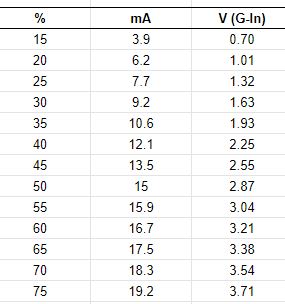
The +Ned Hill post and associated data are here and copied below for reference:

Tube%20power%20percent%20table 

This data shows the important relationship between the digital panels setting [%] and its relationship to the control voltage [V(G-IN)] on the LPS-IN pin and in turn the lasers power level. The LPS-IN signal results in the laser current seen at the ma meter [mA]. 

Observations About the Data

Multiple Linear Regression models can be constructed that more show us these relationships in mathematical form. Perhaps these simple math equations can help us predict the K40's performance and therefore more accurately choose settings.

I ran linear regressions on the above data to see if rational models could be derived to describe the laser powers behavior.

How Digital Panel Setting Control Laser Current Behavior

A regression was calculated using column 1 and 2 in the data above. The below equations represent a model of the relationship between panel settings and the resulting laser current.

equation 1: Tube Current = Digital Panel % * .2784 {R^2 = 0.996}**
equation 2: Digital Panel % = Tube Current/.2784

You can use these equations to estimate the laser current for a given digital panel setting or alternately estimate what panel settings will result in a what laser current.

The **R^2 value and this graph shows that the equations above should be pretty good predictors of laser current for a given panel setting. 

Note: the equation above predicts that at 100% Neds laser should draw approx 28ma of current.

How The Pot*** Setting Controls Laser Current Behavior

A regression was calculated using column 3 and 2 in the data above. The below equations represent a model of the relationship between panel settings and the resulting laser current.

equation 3: Tube Current = Control Voltage * 5.24 {R^2= .999]**
equation 4: Control Voltage = Tube Current/5.24

You can use these equations to estimate the laser current for a given pot setting or alternately estimate what pot settings will result in a what laser current.

The **R^2 value and this graph shows that the equations above should be pretty good predictors of laser current for a given panel setting. 

Note: The equation above predicts that Neds laser should draw 26.2 ma with the IN voltage at 5vdc.

*** the pot is sometimes called "Current Regulation" on stock machines that come with a pot.

How Do I Know What the Pot Setting Is?

Good question! The equation above uses "Control Voltage" as one of the variables so how do you know that value? Install a DVM on the POT. It tells you the control voltage it presents at the LPS-IN pin.

To use this schema read or set the pot until the DVM reads the voltage [control voltage] you calculated using equation 4 above. 

Your Mileage May Vary?

Statistical models are based on empirical data like that given in this post can be in error in a few ways, garbage-in-garbage out. 
+Ned Hills data is likely "IDEAL" since it was taken with a new tube and LPS. As such it should be a great reference as to what a K40 machine can do.

Here are some sources of error (assuming I did the math right):
  • Your LPS is weaker than Neds new one
  • Your Digital panel is defective 
  • The 5v supply used to drive the LPS-IN pin is an incorrect value
  • Your tube is weaker than Neds new one
  • Your mileage may vary

Local vs Programmatic Control

When firing the laser from the control panel the power is entirely controlled by the Digital Panel or Pot Settings. Therefore the equations above apply. 

However when under programmatic control from a PWM signal on the LPS-L pin the lasers power control is more complex. Its power is the product of the controller PWM % and the control voltage on the LPS-IN pin.

Using the Digital Panel To Set Laser Power

Laser current = (PgmPwr/100) * (DigitalPanel * .2784)

whereas: 
  • PgmPwr = the power setting in the control software as a percent
  • DigitalPanel = the setting on a K40 digital panel as a percent

Simple Example:

- DigitalPanel is set to 100%
- Lightburn power setting is 50%

     Laser current = (50/100) * (100*.2784)
     Laser Current = .5 * 27.8
     Laser Current = 13.9 ma

With the above settings when you push the test button you should see the meter read 27.8 ma
When running from program control you will run much less than 27.8 since the static value set by the digital panel will be reduced by any program setting less than 100%. 

Using The POT To Set Laser Power

Laser current = (PgmPwr/100) * (ControlVoltage* 5.24)

whereas: 
  • PgmPwr = the power setting in the control software as a percent
  • ControlVoltage = the voltage on the LPS-IN pin as set by the pot

Simple Example:

- Pot is fully on i.e. LPS-IN = 5vdc
- Lightburn power setting is 50%

     Laser current = (50/100) * (5*5.24)
     Laser Current = .5 * 26.2
     Laser Current = 13.1 ma

Is This Academic Knowledge?

If you expect your system to act exactly like +Ned Hill's then yes this may just be interesting information about Ned's machine. If however you value this information as a model of an ideal K40 machines laser power control behavior more value can be extracted. 

Ideas I have for using this knowledge are:

After taking a few settings *** on a machine you may;
  • See how close it performs to ideal
  • Create a model to match your actual machine by factoring the ideal model
  • Use the model to aid in choosing operational power settings
  • Attain a gauge to track your machines performance as it wears out
  • Troubleshoot laser control problems without electrocuting yourself  
*** take 3 measurements of laser current vs control voltage or digital panel settings.

Donate?

If this post helped you solve a problem, saved you time or was otherwise useful consider donating. Use the link in the upper right of the site.
Donations fund some of the expense of tools and materials for my shop and lab so I can bring you more content like this. 

Also let me know if there is other content you would like to see me explore!
_____

Thanks and please comment
Don
Replacing the K40's Digital Panel with an Analog one

Why replace the panel?

It is not uncommon for the K40's digital panel to fail and more and more users are realizing the value of having a pot for control and an analog meter read laser current.

The digital panel

Understanding the k40 digital control panel

Adding an analog meter.

Adding-analog-milliamp-meter-to-k40.html

Converting the Digital Panel to Analog

Recently +Ned Hill had a LPS failure and tube replacement and decided to replace the digital panel and do a C3D upgrade.
We thought posting the conversion would be useful to others in the community

Schematic

I added a conversion diagram to the existing schematics I had for the digital panel.
It is located on the tab "Convrt 2 Analog".
https://www.digikey.com/schemeit/project/k40-powerled-v30-PM4QJBO303GG/


Conversion Instructions:

These conversion instructions are for supplies with all GREEN connectors. I can add the equivalent for other supplies upon request.

This conversion entails replacing the digital panel with an analog equivalent. The new analog panel has a switch, momentary push-button, pot, and digital voltmeter. The harness that goes from the LPS to the digital panel can be reused with the addition of two wires. These instructions refer back to the schematic.

-Build and mount the new analog panel (blue area)
-Remove the connector from the digital panel (orange area)
-Cut off the connector and strip back the wires
-Reconnect the 4x digital panel wires as shown in the schematic to the new panel (blue area)
-You will have to add 2x wires to the harness the G and the 5V

Note: this schematic also shows an installed pot and an associated control voltage DVM

Extracted from the schematic

Pictures From +Ned Hill Conversion

Supply Connections


Purchase Links

Please buy your parts using my affiliate links. It costs you nothing and it helps fund my activities. I defined a kit for this project which contains all the parts and links to amazon.
The entire kit is here and points you to these parts on Amazon.


Contributors

Thanks to +Ned Hill for his contribution to this post.

Donate?

If this post helped you solve a problem, saved you time or was otherwise useful consider donating using the link in the upper right of the site.
Donations fund some of the expense of tools and materials for my shop and lab so I can bring you more content.

----

Thanks, and please comment,
Don

Saturday, May 14, 2016

Stand alone K40 Zaxis Table & Controller Build


Background

One of the first hacks most K40 makers undertake is some form of table that acts as a base for cutting material. The idea is to have a surface that will support the piece being cut while not catching fire allowing the piece to fall free of the cut. The new K40 user quickly discovers that the distance between the output lens and the piece being cut is a critical setting for getting a good cut. That means that the table must be movable or the piece being cut needs to be shimmed to the correct distance. 

Donate:

Please consider donating (button to the right of this post).

Your donations help fund additional research, tools and parts that I will return to the community as information and how-to's. 

The Honeycomb

The most often first attempt is to procure some honeycomb material from local home improvement stores or to buy a honeycomb platform made for the K40.
I bought one of these and added an adjustable wood platform underneath it so that I could adjust it from above by rotating the 4 bolts. Yup you have 4 adjustments each time you use this and then you need to re-level:
http://www.amazon.com/300X200-Honeycomb-Fit-K40-machine/dp/B00EFFOF0W?ie=UTF8&psc=1&redirect=true&ref_=oh_aui_search_detailpage


Very crude but it worked to get started.

Motorized Z axis

One quickly realizes that having a motorized system for lifting the piece into cutting focus is a good thing to have. Especially since by this time I realized that I would be replacing my stock controller with a better DSP. Short story is that the tool chain for cutting parts with the stock K40 SUCKS. Therefore it made sense to get a motorized system that I could eventually control from the new DSP. I even think that "Auto Focus" is in the cards. I imagined having the design file adjust the table to the correct height automagically....

Light Objects Z axis table

I investigated building my own table and also studied the LO Z Axis table:

I decided that I could not easily build a better one at a lower cost. I wanted to get on with using and learning about cutting on my K40 so I bought the LO table vs playing mechanical engineer.
Z table assembly manual (seriously :( ...)
Limit switch mechanical parts zip. (there are also some parts in here to support LO approach to the control panel)
My goal going in was to make the entire Z axis table modular. All the electronics, limit switches and controls needed to be part of the table and plug into the 24 VDC supply. 
When I get my new DSP I plan to remove the stepper controller and connect the stepper driver to the new DSP.
After reviewing the above LO design I decided to use the LO limit switch part but make my own panel and mounting electronics.

Z axis controller

Here is a place that I figured I would add a lot of value and have some fun coding and building a controller. I actually did build one....... from a Trinket and motor driver from Adafruit.

After a few days of coding my new hardware build .....  I found out I needed a higher power stepper driver than the Adafruit driver could safely handle.
I investigated what LO had and selected a 2A stepper driver. As I was clicking through the LO site I discovered that they had a $20 controller that they sold to drive the table along with the driver. I needed the stepper driver anyway for the new DSP and the store bought controller would again save me time. I put my shop made controller on the shelf and ordered the parts: 24 VDC PS, stepper driver, stepper controller. They arrived and after assembling the table I was ready to wire it all up .....
The parts list:

The LO Z axis build

This was a simple build, just wire it up! Why are the simplest things the the hardest to do. 

Control Panel

The control panel was a challenge because there isn't much room to mount switches on the table and still be able to get to it when installed. I came up with a way to use a single momentary switch which reduced the control panel size.
There is no place to mount the panel so I bent a piece of acrylic and double back taped it to the stepper. 

This puts the control switch in the right back rear of the machine behind and below the gantry. A little inconvenient but I don't adjust the table that much and I gain the modularity that I want. This acrylic is .093 from HD.

Limit switch bracket

I cut the limit switch bracket from .20 acrylic per the LO design in the ZIP (link).
The first time I torqued on the bracket the top tab broke so I ended up modifying it and tie-ing it to one of the posts with a piece glued in at right angles to the bracket. This added piece just has a through hole that captures the post. I had to take the top of the table off to assemble it.

Limit Switches

These limit switches worked for me but you can also get them from LO. 

Controller

The controller doesn't have good documentation, after all this is a K40 adventure and nothing has a map. I did some research and turned up these sketchy links. 
LO provided documentation (I did not use this and in fact did not work)


After wiring it all up I visited controller hell. Nothing worked. God am I glad I made this modular!
I got help from the LO forum. You can see the dialog here if you can get into this forum Troubleshooting the Z table controller.
I never got a set of documents that matched how the switch settings and inputs to the controller actually worked so I moved the table to my bench and started oscilloscope-ing it out. I concluded that the problem was that the controller was not outputting PUL to the stepper driver. Probably cause I had the up/down switch wiring wrong .... and I did. None of the schematics I found worked.
I found that IN3 and IN4 are the DOWN/UP functions respectively and the IN1 & IN2 are the UP/DOWN limit switches respectively. They are all low (gnd) true. I started to draw a truth table for all 4 inputs and both switch positions on the controller and decided that was not productive since I am going to remove this controller eventually.

Optional Speed Control Pot

Various drawings show a 10K speed control pot with the wiper and one end connected across the controller pins SPD and GND. This pot is optional if you want a remotely wired speed control. I did not find it necessary to adjust the speed. If the pot is not installed the on-board pot sets the speed. 

The wiring

Notes on wiring: make sure to check your stepper the wire colors may not be the same as mine. You can find the winding pairs by measuring with an ohn meter looking for continuity between pairs of wires.

The end result is the following schematic: K40 Z axis table schematic @ SchemIT

K40 lift table schematic

Done and Done

So now I have Zaxis control and I am one step closer to my dream of auto-focus. That's another post ......another day.

Here is the final product:
Modular lift table

Installed in machine switch upper right

Access to the switch

Using the table

This is how I hold the parts during cutting:
Studs with threads added.

Studs mounted in a matrix

Studs used above are here!

On to the next hack

If your going to add a LO Zaxis table I hope this build log helps ease the pain and minimizes your research.

Other lift table designs

Here is an impressive and simple design with off the shelf parts. I may have gone this route if it was available when I bought the table.

Maker Don


Friday, November 11, 2016

Click Here for the Index To K40 Conversion

Converting and Improving a K40

I have invested an inordinate amount of time converting my K40 to a better cutting and engraving tool. This post concatenates my K40 conversions posts into a build index. I am doing this with the intention of helping others reduce or eliminate their research, design and build time for K40 conversions.

There are many RIGHT ways to convert a K40 but the most often frustration I see from K40 owners is having a clear and as-simple-as-possible, but not simpler,  set of build instructions that result in a working configuration.
This build log should have everything you need to know to clone my design including parts. If it doesn't or something is missing let me know in the comments or G+ me at:

+Don Kleinschnitz

My approach in this conversion was to start with a clean sheet of paper and engineer the needed modifications. That means that I am analyzing each subsystem, understanding its operation, specifying a conversion design followed by build and then finally verification of performance.

This post pulls together detailed posts for each subsystem with the expectation that in the end it will give the community a specific configuration that works. 

My ultimate intention is for this information to be simple to use for most makers yet detailed enough to satiate an engineer.

Some of this content was designed by myself along with the associated testing and research. However a large amount of content linked in here came from the hard work of others. I just linked things together in a way that made sequential sense to me.

I thank and acknowledge the work of many other members of these communities that contributed in a significant way.

This is a work in progress so expect changes. I will keep this post updated as my analysis/design/build/test and usage evolves.

Donate:

Please consider donating (button to the right of this post).
Your donations help fund additional research, tools and parts that I will return to the community as build and design information and how-to's.

Status

BUILD COMPLETE
Machine in operation testing minor jobs and making repairs and improvements

Advantages of this conversion design?
This design adds the following improvements to the standard K40 experience:
  • Protocol: GCODE enables a better part design tool chain
  • Increased safety: interlocks, mains shutdown, grounding verification
  • Documentation: includes ENGLISH schematics and drawings for everything.
  • Cutting/engraving performance: Air & vacuum assist 
  • Robust DC power supplies
  • Open source software tool chain: such as: LaserWeb, SketchUp, Inkscape
  • Support: a rich G+ community with engineers and experienced laser builders and users willing to help.

DON"T IGNORE THIS!

CAUTION: LASERS AND THEIR HIGH VOLTAGE SUPPLIES ARE BOTH ELECTRICALLY LETHAL AND OPTICALLY DANGEROUS. THEY HAVE THE POTENTIAL TO KILL AND/OR BLIND YOU

STAY AWAY FROM THE HIGH VOLTAGE SUPPLY'S OUTPUT!

WEAR PROTECTIVE EYE WARE AT ALL TIMES WHEN OPERATING A K40!

DO NOT OPERATE A K40 WITHOUT THE PROPER LASER INHIBITING INTERLOCKS INSTALLED AND OPERATING PROPERLY!

BY READING THIS POST YOU AGREE TO USE THIS INFORMATION AT YOUR OWN RISK!

CHAPTER 1: A SIMPLIFIED WIRING DIAGRAM

If you want to get right to the core of the electronics here are the full Build Schematics and below is a simplified sketch of the Smoothie wiring. Pretty one coming soon. The lift table integration is not included on this sketch


CHAPTER 2: THE INTERLOCK SUBSYSTEM

CAUTION! Unmodified K40's are dangerous.

K40's do not come with interlocks however every K40 should have interlocks installed!

The K40 laser is dangerous and can blind you.

Interlocks should be installed on the main cover and the rear laser compartment.

Don't defeat them when your inside the machine. Its not that hard to make an adjustment and close the lid to check the results. 

Wear your safety glasses especially if you have defeated interlocks which I just suggested you do not do!

CHAPTER 3: ADDITIONAL SAFETY IMPROVEMENTS

  • Coming soon, keyed Laser enable switch
  • Coming soon, mains shutdown
  • How to  verify K40 grounds

CHAPTER 4: THE CONTROLLER ELECTRONICS SUBSYSTEM

CHAPTER 5: CONTROL PANELS

I have elected to use two control panels on my K40-S. The stock panel will server as the "K40-S Operations Panel" and the GLCD will serve as the "Controllers Operations Panel. My reasoning was as follows:
  • These two panels have no interconnections with each other
  • I needed more real estate than the stock panel could provide
  • I wanted to make the smoothie and its interconnects modular so I could reuse the packaging for other CNC projects and test it on the bench.

Controller interface panel 

Operations Panel

CHAPTER 6: THE POWER SUPPLY SUBSYSTEM

DC Power 

AC Power

The Laser Power Supply & PWM

Interfacing to the the Laser Power Supply

http://donsthings.blogspot.com/2016/11/k40-laser-power-supply-control-take-2.html#more

Laser Power Supply Test, Repair & Installation

CHAPTER 7: GANTRY SUBSYSTEM

Interfacing to the gantry electronics

Cable management on the gantry

K40 Motors

http://donsthings.blogspot.com/2016/06/k40-s-motors.html

The finder LED

I used a simple approach to implement the finder because I wanted to keep the head bracket simple. The disadvantage of this approach is that the pointer is offset from its true position when the table goes out of the focal range. To date I do not use the finder to locate anything accurately so I am using a single diode vs two with dot or line output. If I do need more accuracy I plan to move the finder so that it enters and exits the light path through the objective lens and therefore totally remove it from the head altogether (more on this idea later).
  • The finder diode is mounted on the head.
  • The finder uses a Laser diode that is mounted in a holder. The holder is adjustable with a screw.


Gantry parts

CHAPTER 8: CABINET MODIFICATIONS

Controller packaging

This packaging design mounts the controller outside the K40 and the DC supplies inside.


CHAPTER 9: Z AXIS SUBSYSTEM

CHAPTER10: LASER OPTICS SUBSYSTEM

CO2 Laser Theory and Operation

Basic Principles of Operation
How do CO2 lasers work
https://en.wikipedia.org/wiki/Carbon_dioxide_laser

Laser Specifications

This is the best reference I have found for laser operating specifications.
http://www.recilaser.com/en/productInfo/fc9181e840aa427d0140aa55363800f1.htm

Laser tube mounting brackets

Mirror mounts and assy. changes

http://donsthings.blogspot.com/2017/01/k40-optical-path-improvements.html

K40 Optical Systems Modelling for Better Alignment

http://donsthings.blogspot.com/2016/06/k40-alignment-tools.html

Aligning, Cooling, Operating and Protecting The Laser

http://donsthings.blogspot.com/2016/07/k40-k40-s-tips.html

CHAPTER 11: THE DESIGN TOOL CHAIN

CHAPTER 12: AIR AND VACUUM ASSIST SUBSYSTEMS

CHAPTER 13: K40 & K40-S TIPS AND FAQ'S

http://donsthings.blogspot.com/2016/07/k40-k40-s-tips.html

CHAPTER 14: TESTING YOUR BUILD

Coming soon...
  • AC power and grounding
  • DC power and grounding
  • Interlocks
  • PWM
  • Endstops
  • Steppers

Appendix A: REFERENCE MATERIALS


Sunday, May 8, 2016

Breadboarding Station

I do a lot of electronics bread boarding and up to now, just like most Makers, have everything flaked out on my bench. For some time I have been wanting to get things more organized making it easier to hack out my embedded controller ideas.
I wanted a work space that includes:

  • Power (5, 9, 12, 24 vdc)
  • Integrated oscilloscope and logic analyzer 
  • Control panel switches pre-wired as input and at lease one LED as output
  • A main power switch
  • Space for an Arduino


Finally, this weekend I set aside time to build my dream breadboard workstation

Oscilloscope

Although I have a nice oscilloscope I found this really impressive miniature oscilloscope that also has a 8 channel logic analyzer function.
http://www.gabotronics.com/oscilloscopes/xprotolab-plain.htm

Xprotolab Plain

I imagined that I could integrate this scope with a bread boarding station. I got one at:
http://www.amazon.com/Xprotolab-breadboard-Oscilloscope-Waveform-generator/dp/B00HWZSAPI?ie=UTF8&psc=1&redirect=true&ref_=oh_aui_detailpage_o00_s00

The oscilloscope is mounted to a right angle acrylic bracket with a set of probes. Well not probes rather these test clips:
http://www.amazon.com/Anycubic-Quality-Analyzer-Folder-Saleae/dp/B014PEB4ZG?ie=UTF8&psc=1&redirect=true&ref_=oh_aui_detailpage_o07_s01


The the Oscilloscope is mounted on a acrylic angle bracket that is screwed to the underside of the base. The clip wiring it restrained to that bracket. Slots were milled in the acrylic to accommodate connecting the clip wiring. The entire bracketed scope can be removed if I want to use it in another location.
This wiring schema keeps the scopes probes short and above the breadboard and out of the way.

Tablet Application

The scope connects to my tablet using this software and an OTG cable:

https://play.google.com/store/apps/details?id=com.nfx.noscpro&hl=en

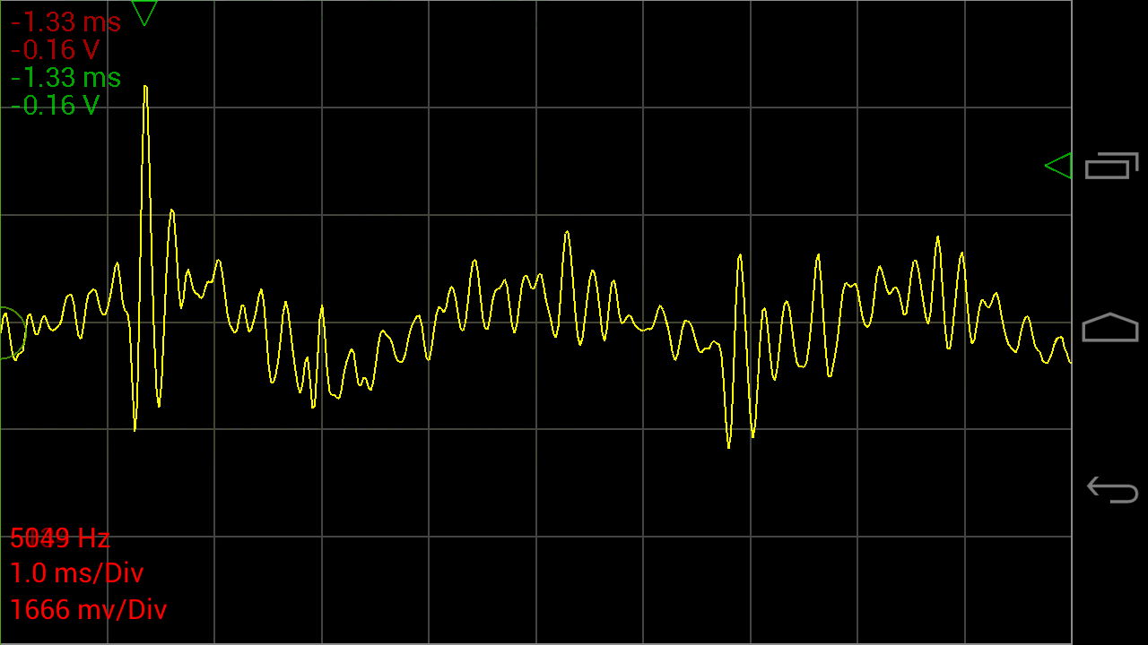
   Oscilloscope Pro- screenshot

You can find a variety of OTG cables on amazon.
The tablet is held with a 2 x 4 that has a 10 degree slot cut in it to the size of the tablets thickness.

Note: I also like to use other tablet based test equipment so this setup affords me access to spectrum analysis, function generator etc.

Mechanical packaging: 

I don't have drawings for the mechanical parts because I designed them on the fly as the build evolved.
The based frame is made from some solid surface (SS) left over from the new kitchen. SS is easy to cut and it can be conveniently tapped eliminating lots of fasteners.
The control panel is fabricated from acrylic sheet (Home Depot) and bent using a shop-made hot wire acrylic bender. "Google" "Bending Acrylic" if you want to build one.

Electrical parts:

The base bread boards is made from 4 of these:
http://www.amazon.com/BB830-Solderless-Plug-BreadBoard-tie-points/dp/B0040Z4QN8?ie=UTF8&psc=1&redirect=true&ref_=oh_aui_detailpage_o00_s00

Four is probably more than I need but I like to prototype stuff and leave it set up until I have converted it to whatever the operation format is going to be, usually a one-of-a-kind soldered breadboard.

Power:

The best power setup i found is to use mini/micro USB for 5vdc and 2.1mm jacks for all other DC. All my power supplied have been fitted with these male and female jacks using these adapters:
http://www.amazon.com/JACKY-5-5mm-Female-Connector-Camera/dp/B00JMVLTA8?ie=UTF8&psc=1&redirect=true&ref_=oh_aui_detailpage_o01_s00


The 3 rear power jacks are for other voltages than 5vdc such as 9vdc, 12vdc and 24 vdc. They are wired though the main power switch and color coded wires are brought to the upper left of the breadboard for distribution.
These jacks are:  5.5mm x 2.1mm Power Jack Socket Female Panel Mount Connectors from here:
http://www.amazon.com/5-5mmx2-1mm-Power-Socket-Female-Connector/dp/B00N41C47E?ie=UTF8&psc=1&redirect=true&ref_=oh_aui_search_detailpage

The 5vdc is supplied by a micro USB connector breakout board. I like to use 5vdc bricks for my logic power. I think the breakout board came from Sparkfun.

All the power is routed through the main power switch ( a 4 pole double throw I found in my stash) for those moments when you smell smoke and want to cut all the power.

Control Panel:

I have struggled for some time with making it easy to add switches into a prototype and then I landed on simply jerking a panel from a old DVD player. This was mounted on the base, it includes 3 buttons and one LED that are wired down to the breadboard on a .1 inch connector strip.

Can't live without an Arduino:

A "biggie" Arduino is mounted on the lower left for those times when I need more compatibility or shield capability, "Arduino" style.

Final configuration