INSTRUCTIONS:

Check out the new MoBeam posts! To find K40 conversion information use the "INDEX", "SEARCH" or "LABELS" sections in the sidebar.
Showing posts sorted by relevance for query GLCD. Sort by date Show all posts

Monday, June 27, 2016

K40-S Graphics Display

Background

The Smoothie supports a graphic display panel which is connected via an adapter board and ribbon cables to the Smoothie motherboard.
The starting point for info: http://smoothieware.org/panel
The  K40-S BUILD INDEX with schematics

Donate:

Please consider donating (button to the right of this post).

Your donations help fund additional research, tools and parts that I will return to the community as information and how-to's. 

GLCD panel Build

The panel and its shield is pretty straight forward to build and install.
  • Shield build
    • Install the missing pins 
    • Install the 5VDC regulator 
  • Plug the shield onto the smoothie
  • Install the 2 shield-to-panel cables making sure they are correctly connected
  • Check the configuration file to assure the panel is enabled and configured correctly
Make sure that you don't make these mistakes:

Configuration

At the time of this post I was running "firmware-cnc"
Enable the panel module and un-comment what is needed for this display.
Link is here: http://smoothieware.org/rrdglcdadapter look for the configuration setting for the GLCD. 

Change the Rotary Dials Rotation Direction & Step Resolution

+Ray Kholodovsky (Cohesion3D):  
In the config file under panel swap the encoder A and B pin #’s with each other.
To change the step resolution; "That's called panel encoder resolution, it's not in the default smoothie config file, but you can add that line in. The value you want is 4, instead of the stock value 2."

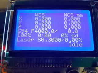
Ready to run, looks like this

Smoothieboard GLCD Shield

The display is connected to the Smoothieboard via this shield which plugs on top of Smoothie :

GLDC sheild without regulator

Mounted GLDC shield with regulator installed

glcdv2_smoothie.png
Note: Additional pins must be added to the Smoothie to accommodate the shield. Install pins in the RED circles.

Cable orientation. I labeled my shield and the cables so that they don't get reversed. 

RepRap Smart Full Graphics Controller:

RepRap Smart Full Graphics Controller

Smoothie board and display mechanical:

In case you want to model the packaging of the display and the smoothie here are some 3D models for SketchUp:

Enjoy and leave suggestions as comments
Maker Don.

Thursday, November 17, 2016

K40-S Lift Table Integration

Background

The K40 bed is fixed and one quickly finds out that being able to vertically position the bed enables a much easier focus process when cutting and engraving objects of various thickness.
I tinkered with building my own lift table and finally realized that that Light Objects lift table was less expensive than I could build myself. This table is used without these build instructions.
Two approaches are described.

  1. The lift function can be made to be stand alone as this post instructs: http://donsthings.blogspot.com/search?q=lift+table
  2. Integrate the lift table with the Smoothie which this post instructs.
This subsystem is added to the K40-S BUILD INDEX with schematics

Thanks to +Robert Rossi  who collaborated and tested this build on his K40.

Donate:

Please consider donating (button to the right of this post).

Your donations help fund additional research, tools and parts that I will return to the community as information and how-to's. 

----------------------------------

Smoothie Integration

Integrating Smoothie with the Light Objects lift table is pretty straight forward.

Limit Switches

You will need to mechanically affix limit switches to the Light Objects lift table. Ideas for mounting the limit switches are included in the Standalone Lift table post. There is a link in this post to a bracket that can be laser cut.

Wiring the limit switches

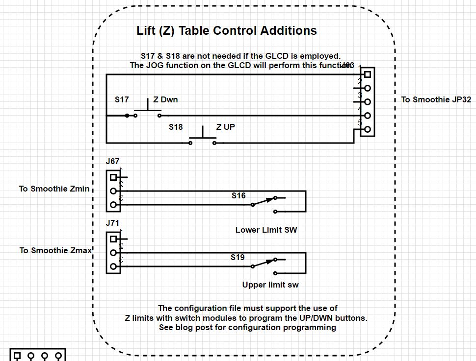
  • Connect the lift tables limit switches to the Zmin and Zmax end-stop connections
  • Configure the z axis in the configuration file
If you are using the GLCD you are done with the wiring. The "JOG" Z axis function on the GLCD will server to move the Lift Table up and down.

Adding UP/DOWN buttons

If you are not using the GLCD and/or want discrete control buttons
  • Connect UP/Down buttons to spare input pins on the Smoothie. I used P1.22, P.23. They can be found on the smoothie board next to the Ethernet connector on JP32. The buttons must switch to gnd.
  • Program the configuration file to use the input switches

Example switch configuration modules:

Up switch
switch.zplus.enable      true                     
switch.zplus.input_pin      1.22^

switch.zplus.output_on_command G91_G0Z10_G90

Down Switch

switch.zminus.enable      true                      
switch.zminus.input_pin      1.23^
switch.zminus.output_on_command G91_G0Z-10_G90

BOM

UP/Down buttons: any NO momentary button will work.

Lift Table Power

I don't know exactly what the power requirements for the lift table is but I do know that it is more than 1 ampere @24VDC. The lift mechanics put quite a load on that stepper.
If you are using the LPS to provide 24VDC to your Smoothie its capacity is only 1 ampere. 

It is therefore possible that you could be overloading the 24VDC supply. Measure the current and voltage when running your Z table configuration to verify you are not overloading the supply. There are no fuses on the 24VDC  from the LPS so if you exceed the load it will damage the internal regulator and you will need to repair the damage or purchase a new supply. (I added DC fuses in my power design)

To minimize power consumption insure that the table mechanics are aligned properly and moving smoothly. Mine had a bent shaft (LO replaced) that cause increased current draw.

Wiring diagram

Go the K40-S BUILD INDEX above to get the latest schematic. 


Monday, January 1, 2018

K40 GLCD Control Panel Housing


My K40-S conversion includes a GLCD and its adapter. After looking at multiple 3D printed enclosures I decided to design one that I could make from 1/4 MDF using my manual mill. I find making one of something is still faster on my mini-mill than traversing the entire tool chain to get to my laser cutter or CNC router :).

More information on the GLDC and its install with Smoothie is here:
http://donsthings.blogspot.com/2016/06/k40s-graphics-display.html

Donate:

Please consider donating (button to the right of this post).
Your donations help fund additional research, tools and parts that I will return to the community as information.
For other information on the K40-S build use the  K40-S BUILD INDEX with schematics. 

The design

I did the design in SU and it is posted here:


The design layers a top, bottom and 3 frame components.
I CA glued the frame components to the top, they act as spacers allowing the electronics to be sandwiched between the top and bottom plates.


  1. The parts were made using 1/4 MDF milled by hand then sanded and painted. Note that clearance had to be milled for the connector pins and the back light which protrudes to the side of the LCD. These features are incorporated in the CAD model.
  2. The panel sandwich uses 2x #4 screws for the top 2 holes and 2x #4 all-thread cut to size with acorn nuts for the bottom 2 screws. #4 nuts are used on all 4 screws.
  3. The top two screws are counter sunk into the top surface with a nut on the back holding the assy. together.
  4. The bottom 2 screws are longer and go all the way through the assy. and into the controller box. These screws hold the panel to the controller box. The panel ends up sitting at an angle since the top two screws nuts are on top of the mounting surface and the bottom 2 screws are under the mounting surface.

The Panel Components


Enjoy and comment
Maker Don

Monday, June 27, 2016

K40-S DC Power Systems Design


Background

This post outlines the design for DC power in the K40-S

The  K40-S BUILD INDEX with schematics

Donate:

Please consider donating (button to the right of this post).

Your donations help fund additional research, tools and parts that I will return to the community as information and how-to's. 

General K40 DCPS design configurations


The LPS capacity:

  • +24VDC @1amp
  • +5VDC @ 1amp
Internally these are created from separate sections of the LPS so they have a total capacity of 29VA.
I do not know the power requirements for K40+smoothie when under full dynamic load and therefore
I am skeptical that 24VDC@1 amp can run everything in this box at full power.

I have not measured the dynamic load so at this point it is a suspicion. Power budgeting & verification is on my list of to-do's.

What configuration to use?

How you wire the DC power depends on what your expected full load will be.
Your full load includes DC current drawn from any/all of these:

  • Smoothie
  • Local Control panel (GLCD)
  • Steppers
  • Z table
  • Finder LED
  • DC pumps


DC Power Budget

Coming soon

Typical configurations


You can configure DC power to the Smoothie in three basic ways:

Way #1

+24VDC from the LPS
+5VDC from regulator installed on-board smoothie
Capacity: 24VA
Pro's: simple two wire connection
Potential Con's: marginal power for anything else, local display, finder led, Z table, pump etc.

Way #2 

+24VDC from LPS
+5V from LPS
Capacity: 29VA
Pro's: more capacity 5VDC + 12VDC
Potential Con's: marginal power for anything else, local display, finder led, Z table, pump etc.

Way #3

+24VDC from external supply with selected capacity
+5VDC from regulator installed on-board smoothie
Capacity: based on external supply choice
Pro's: full DC capacity for K40 + expansion. Simple 2 wire DC wiring
Potential Con's: more complex wiring of AC mains (to add on supplies) and purchase cost of external supplies.

What works?


Many of the K40 conversions use Way#1 and 2, so it seems to work, I just do not know if it is marginal.

I chose Way#3 because:
  1.  I want as much isolation as possible from the HV laser supply. In my configuration only the grounds are common.
  2. I wanted to make sure that the motors had full capacity under dynamic loads. I do not know the actual loads so I took the safe route :).
  3. I wanted extra capacity for future accessories like the local GLCD and driving the stepper for the lift table. 
BTW: I currently use the LPS 24VDC & 5VDC  for other accessories such as external lift table and the finder LED.

You can employ Way#1 or 2 and then measure the PS voltage to insure that it is not drooping.

My Current Design

SCHEMATIC

The design is incomplete and is being documented here:

24VDC:

Separate 24vdc supply to smoothie to run the board and motors.
https://www.amazon.com/gp/product/B018TG7I4W/ref=oh_aui_detailpage_o02_s00?ie=UTF8&psc=1
or:
https://www.amazon.com/gp/product/B00UHI3NGS/ref=ox_sc_act_title_2?ie=UTF8&psc=1&smid=AWUSKMLB3J3ZT

5VDC Power:

Integrated 5VDC regulator on smoothie and Display adapter provides all 5VDC.

http://shop.uberclock.com/collections/smoothie/products/switching-regulator-dc-to-dc-5v

Laser Power Output:

12VDC:

Separate 12VDC supply: pump, cabinet lights, temperature alarm.
https://www.amazon.com/gp/product/B00UHI3NGS/ref=ox_sc_act_title_2?ie=UTF8&psc=1&smid=AWUSKMLB3J3ZT

Fuses:

All DC supplies will be fused using: 


Friday, November 11, 2016

Click Here for the Index To K40 Conversion

Converting and Improving a K40

I have invested an inordinate amount of time converting my K40 to a better cutting and engraving tool. This post concatenates my K40 conversions posts into a build index. I am doing this with the intention of helping others reduce or eliminate their research, design and build time for K40 conversions.

There are many RIGHT ways to convert a K40 but the most often frustration I see from K40 owners is having a clear and as-simple-as-possible, but not simpler,  set of build instructions that result in a working configuration.
This build log should have everything you need to know to clone my design including parts. If it doesn't or something is missing let me know in the comments or G+ me at:

+Don Kleinschnitz

My approach in this conversion was to start with a clean sheet of paper and engineer the needed modifications. That means that I am analyzing each subsystem, understanding its operation, specifying a conversion design followed by build and then finally verification of performance.

This post pulls together detailed posts for each subsystem with the expectation that in the end it will give the community a specific configuration that works. 

My ultimate intention is for this information to be simple to use for most makers yet detailed enough to satiate an engineer.

Some of this content was designed by myself along with the associated testing and research. However a large amount of content linked in here came from the hard work of others. I just linked things together in a way that made sequential sense to me.

I thank and acknowledge the work of many other members of these communities that contributed in a significant way.

This is a work in progress so expect changes. I will keep this post updated as my analysis/design/build/test and usage evolves.

Donate:

Please consider donating (button to the right of this post).
Your donations help fund additional research, tools and parts that I will return to the community as build and design information and how-to's.

Status

BUILD COMPLETE
Machine in operation testing minor jobs and making repairs and improvements

Advantages of this conversion design?
This design adds the following improvements to the standard K40 experience:
  • Protocol: GCODE enables a better part design tool chain
  • Increased safety: interlocks, mains shutdown, grounding verification
  • Documentation: includes ENGLISH schematics and drawings for everything.
  • Cutting/engraving performance: Air & vacuum assist 
  • Robust DC power supplies
  • Open source software tool chain: such as: LaserWeb, SketchUp, Inkscape
  • Support: a rich G+ community with engineers and experienced laser builders and users willing to help.

DON"T IGNORE THIS!

CAUTION: LASERS AND THEIR HIGH VOLTAGE SUPPLIES ARE BOTH ELECTRICALLY LETHAL AND OPTICALLY DANGEROUS. THEY HAVE THE POTENTIAL TO KILL AND/OR BLIND YOU

STAY AWAY FROM THE HIGH VOLTAGE SUPPLY'S OUTPUT!

WEAR PROTECTIVE EYE WARE AT ALL TIMES WHEN OPERATING A K40!

DO NOT OPERATE A K40 WITHOUT THE PROPER LASER INHIBITING INTERLOCKS INSTALLED AND OPERATING PROPERLY!

BY READING THIS POST YOU AGREE TO USE THIS INFORMATION AT YOUR OWN RISK!

CHAPTER 1: A SIMPLIFIED WIRING DIAGRAM

If you want to get right to the core of the electronics here are the full Build Schematics and below is a simplified sketch of the Smoothie wiring. Pretty one coming soon. The lift table integration is not included on this sketch


CHAPTER 2: THE INTERLOCK SUBSYSTEM

CAUTION! Unmodified K40's are dangerous.

K40's do not come with interlocks however every K40 should have interlocks installed!

The K40 laser is dangerous and can blind you.

Interlocks should be installed on the main cover and the rear laser compartment.

Don't defeat them when your inside the machine. Its not that hard to make an adjustment and close the lid to check the results. 

Wear your safety glasses especially if you have defeated interlocks which I just suggested you do not do!

CHAPTER 3: ADDITIONAL SAFETY IMPROVEMENTS

  • Coming soon, keyed Laser enable switch
  • Coming soon, mains shutdown
  • How to  verify K40 grounds

CHAPTER 4: THE CONTROLLER ELECTRONICS SUBSYSTEM

CHAPTER 5: CONTROL PANELS

I have elected to use two control panels on my K40-S. The stock panel will server as the "K40-S Operations Panel" and the GLCD will serve as the "Controllers Operations Panel. My reasoning was as follows:
  • These two panels have no interconnections with each other
  • I needed more real estate than the stock panel could provide
  • I wanted to make the smoothie and its interconnects modular so I could reuse the packaging for other CNC projects and test it on the bench.

Controller interface panel 

Operations Panel

CHAPTER 6: THE POWER SUPPLY SUBSYSTEM

DC Power 

AC Power

The Laser Power Supply & PWM

Interfacing to the the Laser Power Supply

http://donsthings.blogspot.com/2016/11/k40-laser-power-supply-control-take-2.html#more

Laser Power Supply Test, Repair & Installation

CHAPTER 7: GANTRY SUBSYSTEM

Interfacing to the gantry electronics

Cable management on the gantry

K40 Motors

http://donsthings.blogspot.com/2016/06/k40-s-motors.html

The finder LED

I used a simple approach to implement the finder because I wanted to keep the head bracket simple. The disadvantage of this approach is that the pointer is offset from its true position when the table goes out of the focal range. To date I do not use the finder to locate anything accurately so I am using a single diode vs two with dot or line output. If I do need more accuracy I plan to move the finder so that it enters and exits the light path through the objective lens and therefore totally remove it from the head altogether (more on this idea later).
  • The finder diode is mounted on the head.
  • The finder uses a Laser diode that is mounted in a holder. The holder is adjustable with a screw.


Gantry parts

CHAPTER 8: CABINET MODIFICATIONS

Controller packaging

This packaging design mounts the controller outside the K40 and the DC supplies inside.


CHAPTER 9: Z AXIS SUBSYSTEM

CHAPTER10: LASER OPTICS SUBSYSTEM

CO2 Laser Theory and Operation

Basic Principles of Operation
How do CO2 lasers work
https://en.wikipedia.org/wiki/Carbon_dioxide_laser

Laser Specifications

This is the best reference I have found for laser operating specifications.
http://www.recilaser.com/en/productInfo/fc9181e840aa427d0140aa55363800f1.htm

Laser tube mounting brackets

Mirror mounts and assy. changes

http://donsthings.blogspot.com/2017/01/k40-optical-path-improvements.html

K40 Optical Systems Modelling for Better Alignment

http://donsthings.blogspot.com/2016/06/k40-alignment-tools.html

Aligning, Cooling, Operating and Protecting The Laser

http://donsthings.blogspot.com/2016/07/k40-k40-s-tips.html

CHAPTER 11: THE DESIGN TOOL CHAIN

CHAPTER 12: AIR AND VACUUM ASSIST SUBSYSTEMS

CHAPTER 13: K40 & K40-S TIPS AND FAQ'S

http://donsthings.blogspot.com/2016/07/k40-k40-s-tips.html

CHAPTER 14: TESTING YOUR BUILD

Coming soon...
  • AC power and grounding
  • DC power and grounding
  • Interlocks
  • PWM
  • Endstops
  • Steppers

Appendix A: REFERENCE MATERIALS


Sunday, November 6, 2016

K40-S Laser Power Supply Control "Take 2"

K40 Laser Power Supply (LPS) Control

During my journey to convert my K40 to Smoothie control I and many others have been frustrated trying to find a reliable, predictable and understandable means to digitally controlling the K40's laser power. For history see my previous post which I am superseding with this one.

http://donsthings.blogspot.com/2016/06/k40-s-laser-power-control-interface_86.html

CAUTION: LASERS AND THEIR HIGH VOLTAGE SUPPLIES ARE BOTH ELECTRICALLY LETHAL AND OPTICALLY DANGEROUS. THEY HAVE THE POTENTIAL TO KILL AND/OR BLIND YOU

STAY AWAY FROM THE HIGH VOLTAGE SUPPLY'S OUTPUT!


WEAR PROTECTIVE EYE WARE AT ALL TIMES WHEN OPERATING A K40!


DO NOT OPERATE A K40 WITHOUT THE PROPER LASER INHIBITING INTERLOCKS INSTALLED AND OPERATING PROPERLY!


BY READING THIS POST YOU AGREE TO USE THIS INFORMATION AT YOUR OWN RISK!

Donate:

Please consider donating (button to the right of this post).
Your donations help fund additional research, tools and parts that I will return to the community as information and how-to's. 

Simple Smoothie PWM Control 

A simple diagram showing how to connect to the LPS PWM from a smoothie 5x. You only need 2x wires.


NOTE ON CONFUSING LABELING:

In general, driver MOSFET's outputs on Smoothie compatible boards are labeled [+ or VBB] and [- or gnd]. 
The +/VBB is connected internally on the board to a [+] power source it is not a signal. 
The [-/gnd] is connected to the DRAIN of the MOSFET (not ground). 
For open drain connections you want to be connected to what may be marked [-/gnd] pin.  Pick up an actual ground for that signals cable from another pin (like the picture above).


You can remove the pot and install the red jumper which allows the PWM to have full control. I do not recommend this configuration. Although you will have full software control of power you will have to regularly calibrate your machine for max power. See Setting " Power Calibration"

Leave the Pot in

I recommend this approach!

You can elect to keep the "Current Regulation" pot installed in its stock configuration. If you do the actual laser power will be the product of the pot setting AND the PWM setting.

I.E. if the pot is set for 50% power and the PWM is asking for 50% power then the actual power will be:

Actual Power = Current Calibration % * PWM duty cyle

Example: Pot set a 50% and LaserWeb asking for .25%
Power = .5 *.25 = .125 or 12.5%

If you leave the pot in you can allow the software to control the power within its min - max range (0-100%) that the pot is set to. The Pot becomes an overall intensity control and you do not have to calibrate the machine for MAX power.

See this developing post for more detail regarding the PWM configuration effect on engraving:
http://donsthings.blogspot.com/2016/12/engraving-and-pwm-control.html

Actual photo of how my machine is wired


Power calibration

I do NOT recommend taking the "Current Regulation" POT out.

Its my expectation that you remove the pot and pull the IN to 5vdc or set the "Current Regulation" (IN) to full on you will need to calibrate the power settings in your K40-S to keep the power range below the 18ma max operating range.

Power settings and verification

I have not completed the testing on this process but figured those looking for precision control of power would value having a preview. This is less important when cutting than when engraving or carving.

I recommend running a grey scale test and if that images but does not look good I would suggest something is wrong with your settings not your connection to "L".

When using the L line for normal operation with a pot installed you should have it set to a position that limits the current to 18ma and let the controller vary the power within that range. If you have the pot removed and the IN line jumper-ed to 5VDC you have to insure that the driving software never exceedes the max 18ma current level.

Setting the max power

If you are set up right the controller will not exceed the limits set in the configuration and you will not exceed where you want the tube to operate i.e less than 18 ma.

To calibrate:

  1. Verify your max power by using the test button to find out what the max current is with the pot full on. Example: your current meter at max pot setting = 24ma
  2. Then calculate what % you want the max limit of be and set that in the configuration file. Example: 18/24 = .75. You want the max power that the controller ever asks for to be less than 75%.
I advise testing by sending G codes for various power levels and verifying that it stays within limits on the current meter ("Current Regulation Pot"). Make sure the Gcode keeps the laser on long enough to get a good reading on the analog meter.

[later I will post a test for this]

After this is set up the controller should have full control of the power while keeping the power below the 18ma limit. 

You may need to re-calibrate as your laser wears and power levels drop.

Note: this approach to Max power setting may reduce your software's dynamic range for engraving. That is why I do not recommend setting the max power this way. 

See: http://donsthings.blogspot.com/2016/12/engraving-and-pwm-control.html for further development and research.

-----------------------

The remaining sections provide design and engineering information

Thanks for help from these folks .....

Thanks to +Paul de Groot and +Kim Stroman  for providing a schematic and broken power supply, respectively, as a source of information.

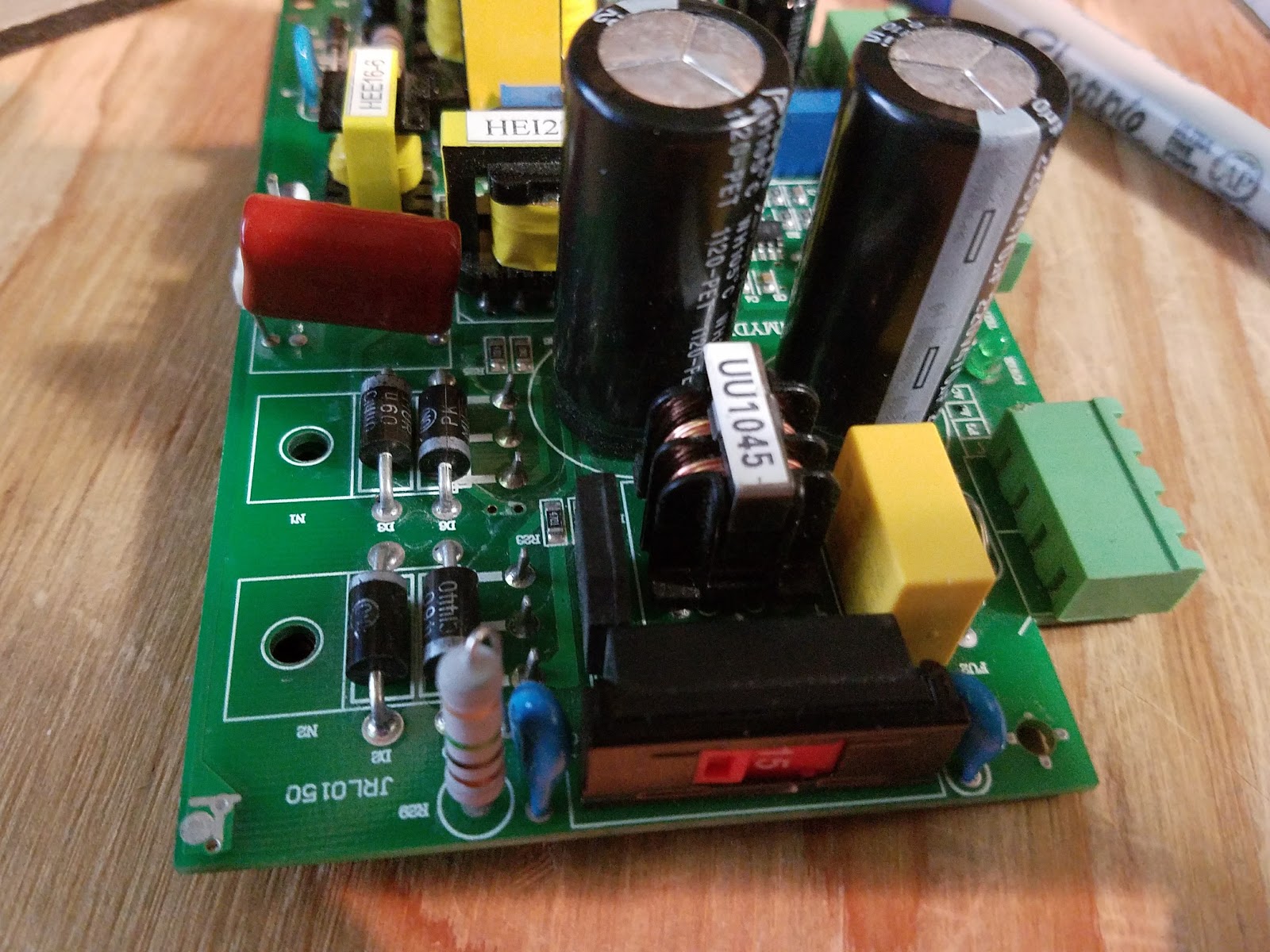
Multiple versions of LPS

We now know that this confusing situation is exacerbated by the existence of multiple versions of LPS's that are in use. Many look the same externally but are different internally.

You cannot tell what type of supply you have by any external means ... that I have found.

Below are pictures of  three few supplies. We have a schematic of Pauls and Kims. Mine I can only poke from outside because it is in service.

Caution: I know there are other versions of LPS out there and this analysis applies to the ones shown in this post. I will add the others as I get samples to trace.

Donate your dead LPS to research

If you have a dead one that you want to donate to this research email me at:

don_kleinschnitz@hotmail.com

PS designation

For this post I am creating a designation for these supplies. To date I have found 3 types and I designated them like this:
  • First letter: the color of the AC power connector
  • Second letter: the color of the control connector
  • Third letterL the color of the DC power connector
  • Third letter: the color of the Power-on LED

Green-Green connectors with Red power LED

Designated G-G-G-R in this post
Photo:
+Paul de Groot's supply

Green-Green with Green power LED

Designated G-G-G-G


+Kim Stroman's supply. Note: flyback disconnected

Green-White connectors with Green power LED

Designated G-W-W-G
My K40 LPS

More LPS style and interconnect references

Schematics:

For G-W-W-G style supply: 

LPS schematic PDF

LPS schematic download (.sch)

For GGGG style:

A share-able schematic that is a work in progress...

PWM circuit sketch not in main schematic yet
PWM circuit

For the G-G-G style supply here are some simplified schematics of the input controls:


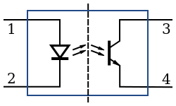
Note that for HV isolation the "ENABLE" and "L" inputs to the LPS are routed through opto-coupler's. The external control signal simply provides a ground to the cathode of the opto-couplers transmitting LED to operate.
In the case of Smoothies open drain control (see PWM Control Via L, below) the opto-couplers LED is connected to the FET's drain and when the FET switches on current flows in the led illuminating it, correspondingly turning on the receiver transistor.


LPS control theory of operation

Although we are not yet finished understanding how external controls are implemented internally on all LPS versions we suspect that from an external perspective the fundamental behavior of these controls are the same.

In general the LPS is switched mode AC-DC supply that controls current with Pulse Width Modulation that drives a flyback arrangement and voltage multiplier. This supply creates a regulated and very high voltage.

AS I NOTED ABOVE: THESE SUPPLIES OUTPUT LETHAL VOLTAGES.

So as to minimize confusion; in a K40 conversion there are two PWM functions at play. The one that is asserted by the digital controller (like a smoothie) and the another that is employed inside the LPS using a PWM IC. These LPS's are designed to operate both stand alone and with a remote means of controlling the level of power.

IMO: When a digital controller is providing PWM control the internal PWM is redundant.  

Basic control function behavior

There are three fundamental control functions on these supplies that are sometimes referred to by different names. I will give them a generic name for this post and also associate them with their real names where I can.

ENABLE: 
The "ENABLE" signal controls the internal PWM controllers output. If Enable is not asserted the laser will not fire because the internal PWM's Duty Factor (DF) is either 0 or in alternative implementations its output is disabled.
  • Ports that behave this way are: TH,TL, K.
At least two ways have been found for how this control is accomplished.
  1. Enable is connected through an opto-coupler that when asserted* enables the output of the internal PWM generator. If enable is not asserted the PWM generator is disabled.
  2. Enable is connected to an opto-coupler who's output transistor is connected to a differential amplifier.  When enable is NOT asserted* it biases one leg of  the amplifier insuring that the IN voltage will not generate a PWM DF > 0. If enable is asserted* the PWM DF will proportionally follow the IN voltage. 
*In all cases opto-couplers in these LPS are digitally asserted by grounding them. These signals are internally connected to the cathode of the opto-couplers transmitting LED.

FIRE:

The FIRE signal enables the output of the internal PWM to run if asserted and remain off if not.
  • Ports that behave this way are: L and Enable #1 above. 
In all the supplies above we have found that FIRE is always accomplished this way:
  1. Connected through an opto-coupler that when asserted* enables the output of the internal PWM generator. If FIRE is not asserted* the PWM generators output is disabled. 
Note 1: The internal "Test" button on the LPS motherboard is connected to this signal through an isolation diode.
Note 2: You will notice that this configuration of FIRE is exactly the same as #1 Enable behavior above. In some supplies it seems that there is an AND function of Enable and FIRE that controls the output of the PWM generator. [more verification needed here].

Power Control (PC)

The PC signal is the means by which the LPS power can be controlled with an analog signal. This signal can be in the form of a variable voltage from a pot or an analog voltage from a remote controller. 
To add to the confusion PC can be overloaded by a digital signal of the right voltage making the IN a power ON-OFF function. More on this further down. 

IMO: this control was not intended to be a digitally controlled input. That is in spite of the fact you will find many configurations and vendors that promote using it as PWM control. 
  • Ports that behave this way: IN
At least two ways have been found for how this control is accomplished.
  1. The IN signal adjusts the current through an opto-couplers input LED whose receiver provides a corresponding and proportional voltage to the PWM generators DF control. This IN signal is isolated and connected to the cathode of the coupler's input diode. In this configuration the IN signal expects a resistance to ground that changes the current in the opto-couplers LED transmitter and correspondingly changes the current in the output transistor. Its note-able that the opto-couplers used in this analog mode and the ones used in a digital mode* are the same component part. The only operational difference is how the current through the diode is provided.
  2. The IN signal is directly connected to one leg of  the internal PWM controllers differential amplifier. When enable is asserted this amplifiers output follows the IN signal adjusting the internal PWM's DF and in turn the output power. When enable is not asserted the other leg of the amplifier is at large enough voltage to prevent the amplifier from outputting a voltage proportional to IN effectively creating a PWM DF of 0. In this configuration the IN signal is not opto-isolated from the supply.
----------------------

Putting LPS PWM control into practice on a K40 conversion

The current investigation and its corresponding espoused theory provide a basis for effectively using PWM control in a K40 conversion irrespective of a specific supply's actual internal operation.

The challenge with defining the RIGHT and WRONG way to configure PWM control of a K40 LPS is that you can make multiple approaches work. The fact that there are multiple unrecognizable versions of these supplies does not help matters. 

Therefore to start with I am going to define how I plan to use the information provided above. Then when I complete building and testing it I will update this post. Other configurations than the one outlined below may work. Its my judgement that the one below is the simplest and most reliable.

Interlock control: 

Leave the stock wiring for the "Laser Switch" and insert in series with this circuit any additional interlocking functions including cover switches and temperature monitors. 

PWM control via 'L":

Connect the controllers PWM function through an open drain (OD) or open collector (OC) to the L pin. Choose a transistor that is connected the controllers PWM function. Insure that in your controller you configure the input to this transistor to assert in such a way that the transistor provides a ground. In other words, when PWM from the processor is TRUE the transistor should be turned on. This transistor is connected to the L pin without any form of pull-up or level shift-er. This pin from the controller will be isolated from the LPS.
In the supplies we tested this signal can be found on the rightmost pin in the LPS DC connector.

A typical Open Drain configuration

The equivalent circuit of the K40-S PWM connection
IN:

Since we are providing digital power control to the LPS through "L" we do not need another form of power adjustment for PWM control but we do for max power setting.
As the laser wears the current required to get the same power changes so the power ranges changes .
Certainly we can change the max-min ranges in smoothies config file but why go through that annoyance.
Leave the pot in and it functions as an intensity control (see Power Settings and Verification above) 
However recognize that the controlled power is the product of the pot setting and the Smoothie PEM setting.
Therefore if the controller is set at 50% and the pot is set at 50% the actual power may be (.5*.5) or .25%. This is because the controller is turning ON the LPS whose power is fixed at 1/2,  1/2 the time .... is that sufficiently confusing :).

More detail at these posts:
http://donsthings.blogspot.com/2016/12/engraving-and-pwm-control.html

Level shift-er use:

It has become common practice to use a level shift-er connected between a 3.3vdc PWM controller signal and either the IN or L signal on the LPS.
I believe that this configuration can be made to work but creates a level of complexity that is unnecessary. Most controllers have Open Drain or Open Collector drivers available. These are less complex to configure and wire and use less parts.

When an OC/OD is not available:

If there are no OD/OC outputs available I would use a discrete circuit that connects to a processors 3.3vdc signal to (R3) and connect "L" to the collector of Q2. Remove R4.

To test this setup. Before you connect to the LPS leave R4 in and connect this circuit to the controller and look at Q2 collector with a scope.  Insure that the collector of Q2 is being pulled to ground with the assertion of a PWM pulse.

I do not plan to test this configuration.

A level shifter circuit I found on the web (untested).

PWM on "IN" with pot installed:

I do not recommend connecting a PWM  control to the IN with a control pot installed. Unless the pot is left in the full power position you will create a complex condition where the incoming PWM is combined with the bias the pots wiper provides. This configuration creates IN bias values that change with the pot position.

PWM on "IN" with no pot installed:

A 0-5vdc PWM signal can be connected to the IN pin without a pot and operate properly. I don't see the value in using this approach as the configuration I recommend gives you the option to keep or discard the pot while providing opto-isolation. This configuration will also require constant max power calibration and configuration settings changes. 

Testing:

The first step was to install the "Simple PWM control" and test its function.

Test the following:

  1. With interlocks open
    1. The laser does not fire with "Test" and/or without the PWM present.
    2. The laser does not fire when the machine is powered down or powered up
    3. The laser does not fire when the smoothie (controller) is reset
  2. With interlocks enabled:
    1. The laser fires when PWM present
    2. The laser does not fire when PWM is not asserted.
    3. The laser does not fire when the machine is powered down or powered up with PWM not present.
    4. The laser does not fire when the smoothie (controller) is reset
  3. The PWM duty factor is controllable from the SMOOTHIE

Signal quality and polarity

Note tests done on a G-W-G supply

Pict#1
Top: PWM from Smoothie
Bottom: PWM at the "L" pin

Pict#2
Top: PWM from Smoothie
Bottom: current in LPS
Pict#3
A table of measures


Above are some scope traces verifying the configuration:

  • Pict#1: The signal looks good and the "L" pin is being driven to the correct levels with the correct polarity.
  • Pict#2: My first try at correlating laser output with PWM. At first glance I am not convinced that the laser is responding properly to this freq of PWM. More testing needed to draw any conclusions.
  • Pict#3: Smoothie PWM with measurements table.
Note: these tests were run using the GLCD "LASER" functions to set and run PWM values.


Index of LPS types

For reference I am including pictures of these PS layouts and packaging.

G-G-G-R:


G-G-G-G


LPS Album

Laser Power Sources

Theory of laser power sources
Enjoy and comment,
Don